Sunday, April 17, 2016

Raj & Abe's Problem Analysis pt.1

For our problem, Raj and I chose the restaurant setting, focusing on the communication breakdown between customers and staff when the time comes to split the bill. By breaking the dining experience into four stages of seating, ordering, eating and paying, we looked for moments of communication between restaurant staff and customers and lack there of.
Our plan was to create a way to easily split the bill as specifically as the customers would want. Instead of billing by seat, we decided that bills could be created after a meal by counting various stacks of dishes the customers create on the table. For input, we looked at the image of the table and height of stacks from above, as well as the table itself as a sensor for different stacks and weights of dishes.
Critique made it clear that the problem and direction we were headed for a solution might not be the best suited for this class. Splitting the bill is a problem that already has several technology aided solutions, and our proposed methods would be extremely difficult to implement within the guidelines of chair table or lamp. Admittedly, I was mainly drawn to this idea because it seemed like a good excuse to repurpose the infrared sensor from the Kinect we knolled. However, Dominick later explained that the data such a powerful sensor produced would likely be too much for an Arduino.

We are currently looking into a completely new situation for a device. Although the critique basically shot down all of our ideas, it also shed light on the option of creating a more poetic object than a functional one. We're keeping this in mind as we move forward.

Holly and Ying and Arduino Experiment

This experiment piece works as an alarm that beeps and flickers according to the level of darkness.


Raj and Abe's Knolling Project | Windows PC Kinect

For our knolling project, Abe and I disassembled a Microsoft Kinect that was part of the PC development kit. The kinect itself was relatively easy to disassemble with few moving parts. Nonetheless, we feel that the sensors and motor retrieved from the Kinect will be invaluable for our upcoming project this quarter.


Our functional diagram (seen above) illustrates how the Kinect takes in user input and outputs that data to a larger processing unit. The Kinect has two cameras and one very powerful IR sensor. In addition, the Kinect uses an array of four microphones to capture a sonic "image" of the room it is in/

Nicola + Xiao's Knolling Project

We took apart a sony Discman which was a handheld, portable CD player. There were a lot of parts inside, and it took us relatively longer time to completely separate every mechanical components. To understand the electronic and mechanical system, we did some research online and figured out how the laser lens pickup and spindle platter worked together.


Minolta Camera Knolling Project: Jun & Lucas

For our knolling assignment, we choose a Minolta Camera. The camera actually had a lot more pieces than we both expected. After opening up the outer shell of the camera, we were able to see all of the gears and bits all connected from the "brain" of the camera. 
An interesting part of the Minolta Camera was how the light was able to be captured and used to trigger the battery. 

In a brief summary, our diagram above shows that by pressing the shutter button, the logic board is able to use a sensor to capture light onto the film. This ultimately imprints the image through a light onto film. Even though this is the bare surface of how a camera works, it was very intriguing to see how many pieces were required in order to create a fully functioning camera. 

Tad Critique – Chaeji Kim & Allison Chan

For our concept critique, we presented a situation involving a baby alone in a crib that would not stop crying. The problem we focused on was how to calm the baby without help from other people.
We explored several different solutions that would involve some form of light source that would soothe or distract the baby so that it would stop crying. One particular focus we looked at was a baby mobile that would turn on and pulse randomly, or to the rhythm of a song once it detected the sound of a crying infant. 
Though we are not exactly sure of the specific direction we would like to move to for this assignment, we received great feedback from Tad and will continue to explore different possibilities.

Knolling – Chaeji Kim & Allison Chan

For our knolling assignment, we took apart a pencil sharpener. It was interesting to note how few pieces the actually pencil sharpener was made up of. There was no processor, and only sensors and actuators that made up how this pencil sharpener worked.
One particular piece that stood out was the rectifier, which is a device that converts alternating current into direct current. In class, we found out that this device was the cheapest way for changing the currents.
The pencil sharpener itself had two main sensors that would both need to be turned on in order for the pencil to actually sharpen. One was pushing the pencil into the hole (triggered by a small button on the side), and the other was a safety sensor that would only turn on if the protective cover was inserted. 
Though the mechanics of a pencil sharpener seemed difficult to understand at first, we were surprised at how simple the system worked after taking the pieces apart and examining them ourselves.

3–5: Situation, Sensing, & Logic Descriptions — Jun & Lucas

The scenario we presented started as an automatic baby monitoring device, and evolved into  capturing the movement and sound created by a baby in a crib and turning it into light—essentially, a baby monitor for the deaf. The inputs could be any of: movement, sound, gas, or stasis (no input), and the outputs we explored include light pulses or strobing, vibration or other movement of a chair, a lullabye played for the baby, or an alarm sound (this last one obviously would not work for the deaf or hard of hearing).

The direction we decided to move in, based on Tad's input and our discussion, is to reflect the behavior of a baby with a light, probably using piezo (and perhaps additional) microphones as inputs. The goal is to bring a parent closer to their baby with a lamp that ideally rests firmly in the upper right quadrant of the usefulness/poetic coordinate plane.

Logically, it will work by monitoring the sound and movement of the baby and transforming that behavior into light. The logic will be along the lines of: if there is sound/movement, create light. Depending on how much activity, as well as its intensity and volume, change the light accordingly.


Arduino Experiment - Natalie & Logan

For our experiment, we wanted to make the Arduino unit know if it was upside down or not. By measuring the resistance of the tilt switch, the Arduino would light up the green LED to indicate that it was right-side up or light up the red LED if it was upside down.


Tad Discussion- Logan and Natalie

For our idea, we decided to go about thinking about a lamp, and what we might be able to do with that. After thinking about a variety of options, we thought that something that might be interesting and useful (and hopefully at that intersection between poetic and usable) was a "lamp" that would help you find something in a room. We came into this idea very broadly, as we thought that was a space that needed some help, as people are often attempting to find their keys or wallet and are forced to search all over rooms in order to find them, but really only the 'Find My iPhone' application exists. After discussing it with the class and Tad, it was clear that we were headed in the right direction- but the important part was to find a way to make it tangible and realistic. We spoke about taking a string of lights around a room, and using the string like X and Y axises that would pinpoint where in a room an item was, and using some sort of sensor before hand that knows the shape of the object, and then directs light at the object. If it was in every room, a person would know immediately that the item was not in the said room if no lights were on/no lights were bright on the ceiling string. We're excited to move forward with this idea, even though it's not entirely formulated exactly how we'll do it- but that's something that makes it interesting, as right now it's open-ended, and we need to figure out how to do it functionally with the materials we're able to use and produce.

Knolling- Logan and Natalie

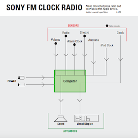
For our knolling project, wetook apart a Sony Alarm Clock with Radio and an iPod dock. This knolling assignment was interesting, as we both had worked in knolling before but never attempted to understand what it was we were taking apart. Below is the image:

While taking it apart, we took note of what sensors were connecting to the "brain," and through what elements (like buttons). We saw that most everything was going into the brain of the piece, or the larger green circuitboard shown, and realized that was the element that made the outputs happen, like turning the object on and off, or making it go to sleep, etc.

While being relatively small, it is clear that much can be done in terms of visual display and sound after using this product, and how important every little piece is in making this product functional.

Xiao + Nicola's Critique w/Tad 

The concept we proposed during our critique with Tad was basically a scenario where people who are sitting down are automatically brought to matching eye-levels. We had a range of input ideas, from IR sensors measuring heights to wearable hats that sense height difference. We were excited to think of something that sort of affects social behavior, but after some critique decided it wasn't that compelling. It did prompt us to think about socially aware furniture, which we'll continue to consider in moving forward.

2) Dillon and Dwight's Knolling Project

We disassembled a digital alarm clock for our knolling project. This alarm clock had a seven-segment LED display, volume control, time adjustment, and AM/PM indicators.
We were surprised to find that such a small, simple alarm clock had a fairly intricate circuit board and inner workings. We're excited to move forward and use many of the pieces from this alarm clock for future prototypes, especially the LED screen.


3) Dillon and Dwight - Situation Description

When presenting our initial ideas for the Arduino project, our guest lecturer Tad gave us some great insights. We decided to aim to create an interactive lamp that spins and tilts according to a certain input. We have not nailed down exactly what input we want, but our initial idea is using some sort of sound or motion sensor. We placed ourselves high on the poetic scale and decently high on the useful scale. We are excited to start the process of learning the electronics and building the actual lamp.

The intended lamp will be primarily used as a self-tracking spotlight that will follow users with a crisp bright beam of light. Our assumed use-case would be during events or performances given on stage such as speeches, dances, or any other event placing someone on stage in need of illumination. We intend to use infra-red light to create a signal between the user and the device. The user will either hold or be wearing an object that would emit a high level of IR light and the device will be assembled with a series of IR sensors and programmed to point in the direction that is giving off the most IR light in the room. We realize that the largest source of IR light on the planet is the Sun, however we don't see this as a problem since most of our users wont need a spotlight unless they are indoors or it is dark enough outside that the Sun's emission would not trigger the sensors.


Dillon and Dwight's Arduino Assignment

Our plan was to calibrate the Arduino board to change the color of a 3-color LED between red, green, and blue, depending on the rotation of the knob.


Peter + Kylen: Knolling a Conair Phone


We took apart a 1980's Conair telephone for our knolling experiment. The inner workings of a telephone were a lot simpler than we anticipated, which we attempted to explain in our diagram.
The model is one that consumers would take home and build themselves so a couple of the screws were totally stripped. Luckily Raj was able to help us remove them with a power tool.


Holly, Ying, and the Clairvoyant Lamp

Ying and I propose a lamp that reduces the occurrence of anxiety in traditionally "safe" spaces such as private homes. We hope to have the lamp achieve this by detecting movement towards a door or some other object that obscures vision, and then illuminate gradually to reflect the distance and rate that the person is approaching the obstruction. A hero scenario that we envision involves a teenager in their room who may be in a compromising situation (or otherwise socially-unprepared) and would like warning before their parents - or some other person - knocks on the door and enters. This would allow the preservation of privacy, as well as a non-intrusive means of security.


We brought a broad spectrum (private to public; indoor to outdoor) of the concept to present to the class last Wednesday. As a result, our feedback from the class critique raised questions of whether our concept was necessary, as we may as well "invent the window." However, once we described the specific situation with the teenager, the concept became more compelling. Additional questions include how detailed the lamp should get when warning of the user of the approaching figure, and what form the lamp should take within the room (wearable, stationary, etc.)

First Critique

While we were brainstorming ideas for the initial critique we began discussing personal interactions with lamps. Both of us have lamps on the main floor of our houses as the sole light source for the room. They often get left on overnight, the last person to leave not wanting to be alone in a dark room. Our concept has obviously been done before, but we thought of a light that would turn off when it stopped detecting a presence in a room. Although unoriginal, we tried to think of output signals that could indicate it was about to turn off so no one would be left in the dark :~)

Tad pointed out that it's pretty boring and that we would not care about this project and we agree, so we have moved on to a new concept: to create a "mood lamp". This lamp would receive input from either heat, pressure, or location of the hand, and change color. We are looking into different sensors and actuators to make this possible.

Peter + Kylen = ~*~Arduino Logic Experiment~*~

We placed three LED lights onto our board, and made them correspond to the changing resistance. By changing the output of the sensor, the green, yellow, and red lights illuminate at different times. Green at the lowest voltage, yellow at the middle, and red at the most.


Our Code:

int led = 9;// the PWM pin the LED is attached to
int knob = 0;
int brightness = 0;// how bright the LED is
//int fadeAmount = 5;    // how many points to fade the LED by

void setup() {
  Serial.begin(9600);
  pinMode(led, OUTPUT);
  pinMode(A0, INPUT);
}

void loop() {
  analogWrite(led, 0);
  knob = analogRead(A0);

  if(knob < 400) {
    led = 11; //green
    Serial.print("green light ");
  }

  else if (knob > 400 && knob < 700) {
    led = 10; // yellow
    Serial.print("yellow light ");
  }

  else { //brightest
    led = 9; //red
    Serial.print("red light ");
  }

  Serial.print("knob is ");
  Serial.println(knob);
 
  brightness = map(knob,0,845,0,255);
  Serial.print("brightness is ");
  Serial.println(brightness);
  //brightness = brightness + fadeAmount;

  //if (brightness == 0 || brightness == 255) {
    //fadeAmount = -fadeAmount ;
  //}
  analogWrite(led,brightness);
  delay(200);
}

Jane Zihan Team: Lamp for stress proposal


This was our idea at first. We think lamp is a personal object that can extends its involvement with human even further. So we think a lot of things on human body can indicate whether a human is in stress. It could be an opportunities for us to design a lamp that detects the stressful emotion and helps him to get rid of it. We didn't come up with a clear direction for the solutions. 
During the critique, we learned that what we are trying to achieve is very personal and the ultimate solutions to stress could be very complicated. Tad and the class proposed that instead of focusing on how to remove stress from a person completely, we should focus on learning what the humanistic way to help de-stress are there and how can we use a lamp to support that process. 

Jane Zihan Team: Toaster Knolling

During a scavenge hunt in GoodWill, we decided to take apart a toaster for knolling project. Questions we had before we took it apart?
How does a toaster switch between on and off?
Is there any heating sensor controlling the temperature inside?
How does the toaster keep the slider down?
After we took it apart, we found out that by pressing the slider down and stretching the spring side, AC power is then connected to the toaster. Once the power is connected, the heating elements inside are immediately switch on. Couples of resistors are found inside to keep the temperature from going too high. The electromagnet is the one that keeps the slider down. And the only logistic part inside is the timer. It cuts the power from the electromagnet, then release the slider and stops heating. Spring force released, pushes toasted breads into the air. Bang. Breakfast.  

Saturday, April 16, 2016

No. 3 - Table Project Concept: Andrea + Nick

Our concept involving a table is centered around the potential social anxiety of having to share a table with a stranger, approaching a stranger to ask if you can share your table, or wanting to avoid others at your table. Often times, people occupy more space than they need, but also would be willing to share when asked. A lot of this discomfort can stem from the lack of clear indication if a space is wanting to be shared or not, and whether the person occupying the space already would be willing to comply to sharing when prompted. 
With this, we had the idea to use Arduino to allow a table to communicate the sentiments of its occupants or notify those looking for a place at the table, whether its available or not. 


No. 2 - The 100th Alarm Clock Knolled by Andrea and Nick


We took apart this GPX touch sensor (snooze) dual AM/FM radio alarm clock. Made in the 90's, its age reflected in the cleanliness of it's circuit board (it was not clean) and perhaps the excess of parts that in modern alarm clocks have all been consolidated for in more efficient ways.


Through taking this apart, we realized there were two channels and functions that this clock served. For one, it was a clock, where hour and minute are displayed on the LED. It also had the ability to be an alarm with 2 different presets, and then it was also an AM/FM radio. These two purposes combined allowed the alarm to turn on the radio when activated (which in turn, turns on the speakers and can be adjusted with volume and tune actuators). 


Ying and Holly Knoll a Calculator!

For our knolling assignment, Ying and I took apart a Sharp EL-233S handheld basic calculator. While it was simple enough to remove the screws from the outer shell, the part of the process that required the most negotiation was prying apart the shell by wearing away the compressed plastic parts that bonded one half of the shell through the processor chip and to the other half. After that, like a shucked oyster, the calculator revealed its squishy innards.


We had already expected that the processor chip, as the "brain" of the calculator, handles the logic of its calculations. Still, on its own it does not handle translating the physical input into binary logic, or outputting an LCD display. We were surprised to discover that the calculator contains a membrane that not just provides the tactile feedback one gets from pressing the buttons, but also contains the carbon that conducts with the back of the processor chip, thus relaying the user's input to the brain. 

The logic of the processor chip as well as the mechanics behind the LCD screen are described below in our function diagram:


Xiao + Nicola's Arduino Logic


We attached three LEDs (red, yellow, and green) and had Arduino light them according to the level of light sensed by the photocell sensor (red when it's darker, green when it's lighter, yellow in between). Our light sensor was acting funny so we had to set the parameters to very small: <665 was dark, above 668 was light. This would be more interactive if we could get our sensor working!

The Effect


The Code


Friday, April 15, 2016

Maureen + Sarah, Knolling

Week Two

For our Knolling project, Sarah Oakes and I took apart a Steam Iron. It was an interesting, complex item to take apart.

Here's how we laid out the components after we took apart the iron:

After we took it apart, we tried to figure out what each component contributed to the iron.
According to the assignment description, "remember to think in terms of computers (components that make decisions), sensors (components that detect actions), and actuators (components which make something happen)." 

Heating actuators ran along the underside of the iron to heat up the hot 'iron.' Another actuator, the heat safety shutoff, is susceptible to melting so as to end the circuit connection in the case of the iron over heating. The heat intensity sensor receives input from the user (spinning the dial to the correct setting) and with help from a computer component, determines the amount of heat generated. The computer connects or breaks the connection to the heating depending on where the heat setting sensor is dialed to. For extra steam, the user can press a button (sensor) that causes an actuator to open the tube and send out extra steam.

Wednesday, April 13, 2016

Holly Chan and Ying Zheng Arduino Blink

1. change speed


2. alternate blink


3. count


Tuesday, April 12, 2016

Pete and Kylen making it happen with arduino

Alternating:
void setup() {
  pinMode(13, OUTPUT);
  pinMode(12, OUTPUT);
}

// the loop function runs over and over again forever
void loop() {
    digitalWrite(9, HIGH);
    delay(500);
    digitalWrite(13, LOW);
    delay(800);
    digitalWrite(9, HIGH);
    delay(800);
    digitalWrite(13, LOW);
    delay(500); 
}

Changing Speeds:
void setup() {
  pinMode(13, OUTPUT);
  pinMode(12, OUTPUT);
}

// the loop function runs over and over again forever
void loop() {
    digitalWrite(9, HIGH);
    delay(300);
    digitalWrite(13, LOW);
    delay(900);
    digitalWrite(9, HIGH);
    delay(900);
    digitalWrite(13, LOW);
    delay(300);
}

Count:

void setup() {
  pinMode(13, OUTPUT);
  Serial.begin(9600);
}

void loop() {

  int count = 0;

Dillon and Dwight - Arduino Assignment

1) Change the speed at which the light blinks.


2) Alternate blinking between two lights.


3) Increase the amount of blinks by one for each stage.

Xiao + Nicola's Arduino Magic

1. change speed of blinks

we programmed ours to blink on for 5 sec, 
off for 1, on for 0.5, off for 10

2. alternate blinks between two lights


one light uses the output at 13, and another at 12

3. count every blink


 we programmed ours to print (to the serial monitor) 
the value of a variable called "count" every time 
is runs through the loop which causes the light to blink