As computing becomes more ubiquitous in our objects, designers need to be more aware of how to design meaningful interactions into electronically enhanced objects. At the University of Washington, a class of junior Interaction Design majors is exploring this question. These pages chronicle their efforts.

Friday, June 12, 2020

Xiaomi Mi Watch Teardown + Knolling


Teardown of Xiaomi Mi Watch

Used https://www.ifixit.com/Teardown/Xiaomi+Mi+Watch+Teardown/130132

My biggest takeaway from this teardown was really just how each of the sensing components works. I'm familiar with what their functions are, such as "detects sound" or "senses heart rate", but I'd never really considered the "how". Thus, I had to conduct some independent research into each component (see: the callouts in my knolling image above). In particular, I was surprised to learn that the heart rate sensor relies on light reflections to track pulse. My initial guess was that the heart rate sensor is somehow able to detect the slight vibrations of one's pulse point, but I suppose that that would require a very high degree of sensitivity that is unlikely for this product.

I wasn't able to find out the functional ins and outs of each of the processing components, but their names give some indication as to their purpose. For example, the Qualcomm WCN3620 wireless connectivity chip is likely what allows for the watch to connect and exchange data with other Bluetooth devices. Additionally, the T9897 music audio IC might be what allows the watch to process the electromagnetic current generated by the microphones when detecting sound. This is something that I'll continue to look into.

Tuesday, June 9, 2020

Physical Computing 325 Final
University of Washington
Jack Kramer


For my final project, I decided to make an arduino modulated humidity responsive plant germination unit. The original plan was to use a photoresistor to determine when the grow light would turn on, as well as a homemade humidity sensor to send data to an LCD as a means of alerting me when I need to water the plant. I got a little over halfway there before I killed my power supply, this is my journey. 


I started with the grow lights. I bought some inexpensive basic lights off Amazon, there wasn’t anything super special about these other than the fact that they had an easy clamp attachment mechanism. I didn’t know it at the time, but these lights are actually powered through a USB wall adapter, which meant they could be powered off a 5V lead. 

Before I could do anything else, I needed to snip off the USB power connection and gain access to the 5V and ground wires. I snipped above the light timer that came with the unit; I didn’t want the internal control unit to mess with the voltages or program, so I just cut above. 

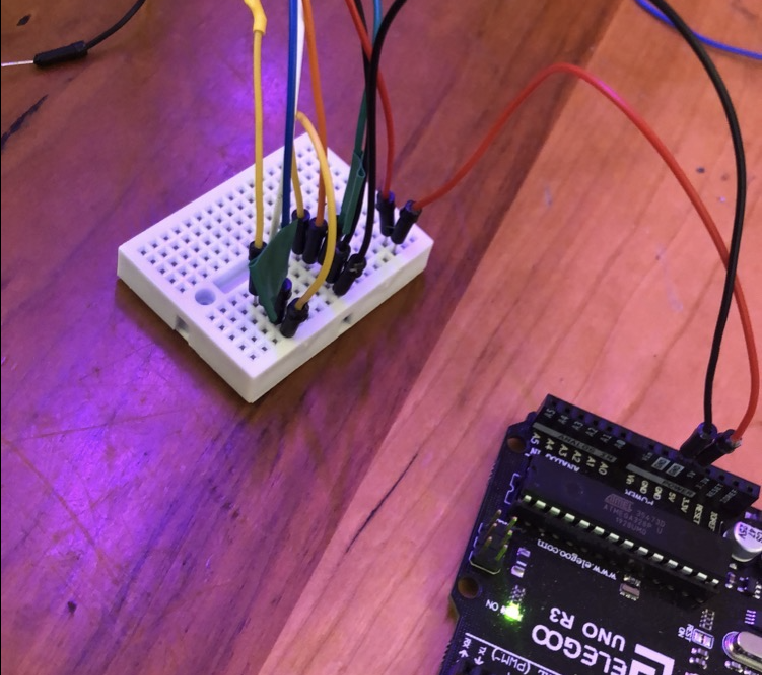
In an unexpected twist, I got seven wires instead of two. Red, green, black, blue, yellow, brown, and white. Through some trial-and-error I was able to determine which were grounds and which were power, which I organized on the mini breadboard that came with the arduino kit. 


I then proceeded to plug the 5V into the 5V lead on the Arduino and the ground on the Arduino GND, and it worked! I knew my solder job was solid and I got all the leads right. 


Unbeknownst to me, this was actually a huge problem. The arduino was built for control, not power; I needed to power the lights with an external power supply AND build a relay circuit to control the voltage. 

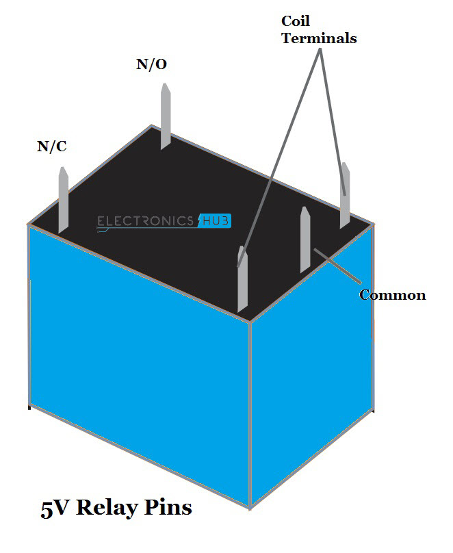
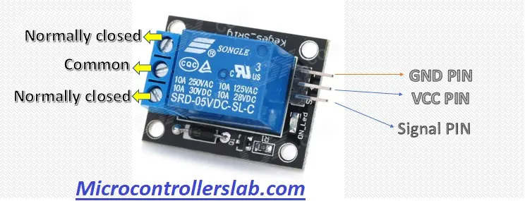
I used this guide to build the relay circuit using a Songle SRD-24VDC-SL-C. I encountered a small problem with the pinout, seeing how the relay provided with the kit didn’t come with a PCB to allow for easy setup. The one I got had five pins and ALL the guides used the PCB relay, which had six pins. 


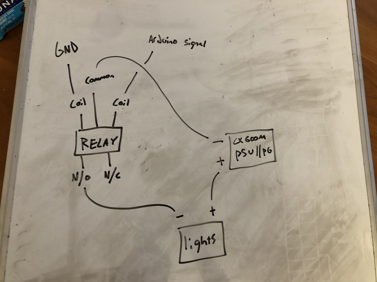
This actually turned out to be a pretty easy fix- the N/O (normally open) pin would go directly to the negative lead of the light, and the N/C (normally closed) pin would be left alone. One of the coil terminals would go to the ground lead on the breadboard, and the other would go to the arduino signal pin (I used ~10). Finally, the common pin would go to a GND pin on the external power supply, which would also provide a +5V lead to power the lights. 

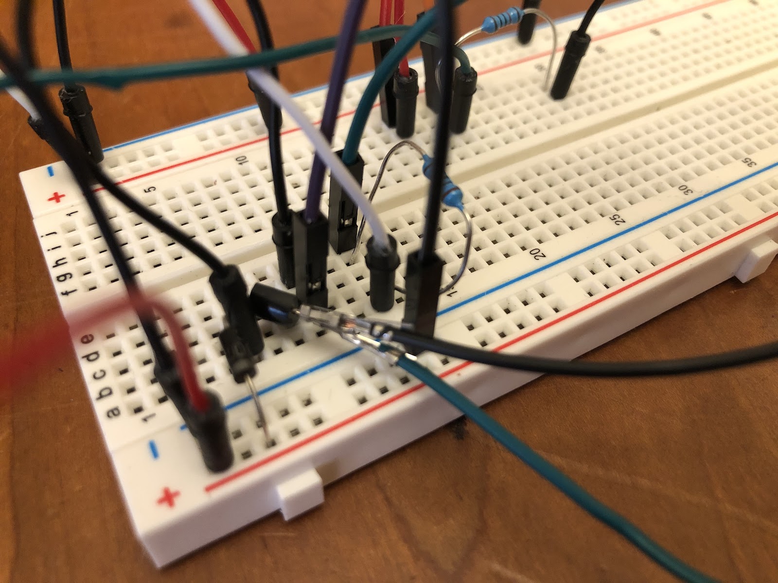
The final step was to get the 1N4007 diode and the 2N2222 transistor set up correctly, seeing how the PCB controlled version of the relay had it built in; this was simple and resulted in the following wiring:


Now I had to figure out a power supply to run everything. I gutted an old Dell and came up with this bad boy- 


Dell doesn’t provide pinouts for their proprietary power supplies (PSU), so I had to use a multimeter to determine which pins provided which voltage on the H240EM-00. I came out with this pinout- 


I couldn’t use the 4-pin, seeing how the 12V lead was way too powerful. I actually tried the circuit with the 12V, and after a couple seconds the mini breadboard started to smoke. A 5V was required. The 8-pin had more variation in the voltage outputs, but the only problem with this was that one of the two pins used to jump the PSU happened to be the +5V (green), so when I tried to use that lead it didn’t give any power to the circuit. The -5V didn’t work. I had to find another PSU. 


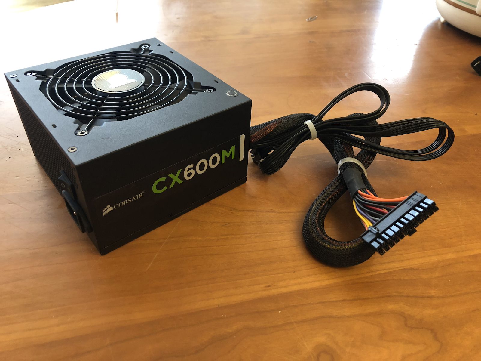
Enter the Corsair CX 600 M. 


I didn’t care that it was three times as powerful as the Dell, all that mattered was that it had a standard ATX pinout, a diagram that was readily available on the internet. No more multimeter was needed. 

Now I had unobstructed access to multiple +5V leads, seeing how the PS-ON pin was a standalone function pin. Perfect. The last step was to implement the photoresistor. 


I connected it all with the following code!

This told the arduino to turn the lights on if the photoresistor received no light- when the sun set, the grow lights would turn on! 

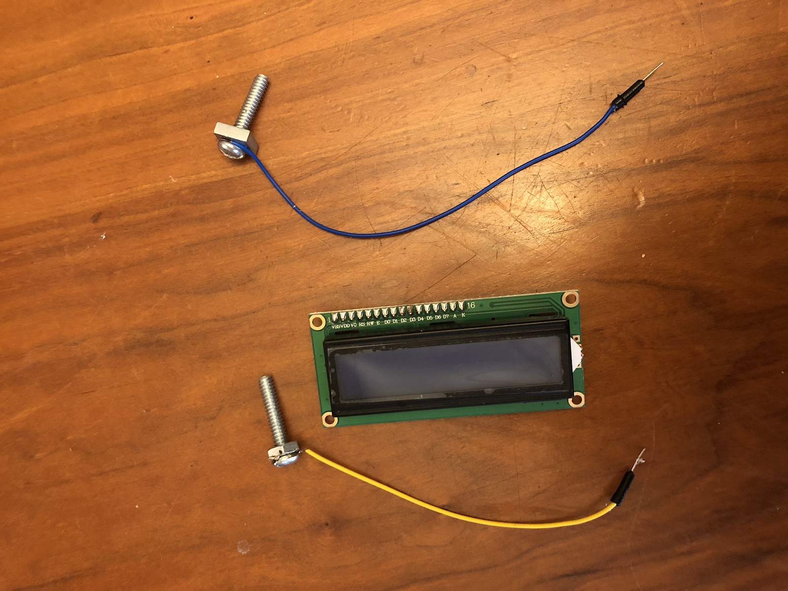
Now I started to work on the humidity sensor. There are premade soil sensors like this one, but I decided to make one out of screws using this guide. I started by taking two screws and some wires and soldering the wires to the screws after securing the wire to the screw with a nut. 


However, that’s as far as I got before the PSU killed itself. I don’t know what I did wrong, all I know is that it doesn’t turn on anymore. 

If I had continued along, I would have used the guide above, combined with the LCD, to write out the sensor readings on another mini breadboard to produce an easy-to-read module to let me know when to water the plant, with the “digitalWrite” function could have been adapted to the LCD using the “lcdPrint” function. 

A new PSU is on the way, we’ll see what happens :) 


Monday, June 8, 2020

Processing Experimentation: Contiunued Lines

I altered the example file “Continued Lines”.


One of the things I did was make the stroke width randomize with each frame. I did this using the strokeWeight + the random function. I also altered the code so that each time you click, the range of colors displayed as you draw your line changes. I did this with a few cascading if /if else / else statements that only ran when the mouse was pressed. When the mouse was released, the else statement generated a random number between 0 and 3, and this was stored in a float. This number was used to determine which color range would be used the next time I drew a line.


/** * Continuous Lines. * * Click and drag the mouse to draw a line. */ float lineColor; void setup() { size(640, 360); background(102); } void draw() { if (mousePressed == true) { if(lineColor * 3 > 6){ stroke(random(255), random (255), 255); strokeWeight(random(100)); line(mouseX, mouseY, pmouseX, pmouseY); } else if(lineColor * 3 > 3){ stroke(255, random(255), random(255)); strokeWeight(random(100)); line(mouseX, mouseY, pmouseX, pmouseY); } else{ stroke(random(255), 255, random(255)); strokeWeight(random(100)); line(mouseX, mouseY, pmouseX, pmouseY); } } else{ lineColor = random(3); } }

Tuesday, April 7, 2020

Time Difference Clock


Clock with timeDifference variable. Able to manually insert the time difference to the code to get the time of anywhere you want to know the time of.


Although the modifications to this code are not extensive, I wanted to take the time to figure out how the code works. The code gets values from the computer clock and translates it from a numerical value to radian values so that it can rotate visually around a center of the display window. My modification is a simple one where I added a float variable, timeDifference, so that the user can change the time difference of a location they want to know the time of. The timeDifference variable is added to the existing code before the code translates it to radian values. I also made the second's hand red.

Monday, April 6, 2020

Clock code modification

I first changed the size of the actual popup from a rectangle down to a square that just barely fit the minute ticks- no point in having horizontal space wasted on the screen, only the essentials! 
I then made the background fill from (80) to (500), promoting a simpler color scheme and allowing the user to focus on what’s important; I didn’t see the point in the inclusion of an ugly off-grey circle. 
Next, I altered the thickness of the different hands on the clock. I felt like there wasn’t enough differentiation between them, so I made the second hand half as thick, kept the minute hand the same, and the hour hand 1.5x heavier; now it’s a lot easier to differentiate between them!
Finally, just for fun, I made the actual minute ticks 5x larger; I feel like it “completes” the look for whatever reason. 
/** * Clock.  *  * The current time can be read with the second(), minute(),  * and hour() functions. In this example, sin() and cos() values * are used to set the position of the hands. */
int cx, cy;float secondsRadius;float minutesRadius;float hoursRadius;float clockDiameter;
void setup() {  size(360, 360);  stroke(255);    int radius = min(width, height) / 2;  secondsRadius = radius * 0.72;  minutesRadius = radius * 0.60;  hoursRadius = radius * 0.50;  clockDiameter = radius * 1.8;    cx = width / 2;  cy = height / 2;}
void draw() {  background(0);    // Draw the clock background  fill(500);  noStroke();  ellipse(cx, cy, clockDiameter, clockDiameter);    // Angles for sin() and cos() start at 3 o'clock;  // subtract HALF_PI to make them start at the top  float s = map(second(), 0, 60, 0, TWO_PI) - HALF_PI;  float m = map(minute() + norm(second(), 0, 60), 0, 60, 0, TWO_PI) - HALF_PI;   float h = map(hour() + norm(minute(), 0, 60), 0, 24, 0, TWO_PI * 2) - HALF_PI;    // Draw the hands of the clock  stroke(255);  strokeWeight(.5);  line(cx, cy, cx + cos(s) * secondsRadius, cy + sin(s) * secondsRadius);  strokeWeight(2);  line(cx, cy, cx + cos(m) * minutesRadius, cy + sin(m) * minutesRadius);  strokeWeight(6);  line(cx, cy, cx + cos(h) * hoursRadius, cy + sin(h) * hoursRadius);    // Draw the minute ticks  strokeWeight(10);  beginShape(POINTS);  for (int a = 0; a < 360; a+=6) {    float angle = radians(a);    float x = cx + cos(angle) * secondsRadius;    float y = cy + sin(angle) * secondsRadius;    vertex(x, y);  }  endShape();}
x

Saturday, April 4, 2020

Processing Experimentation: Exploding Puppy


From the original demo "Explode" by Daniel Shiffman, the program takes an image and divides it into tiny pixel squares that create an explode effect outwards in the z-axis as the user moves the mouse laterally across the artboard. 


In my edit, I wanted to emphasize the "explosiveness" of the motion and increased the z distance of the pixels. I also changed the pixel size and shape to circles from squares, adjusted the artboard and position of the photo, as well as changing the image to a picture of a puppy. 


However, I noticed that in the demo above, the pixels that are in the darkest part of the image (the puppy's nose) were the last to leave the artboard. Curious, I explored how I could manipulate the order in which the pixels would "explode." The expression in line 31 tells us that as the user moves their mouse at a certain y-coordinate, it manipulates the pixels based on it's brightness. The brightness is affected by how much light is in a hue and the color values range from 0 to 255. Taking that in mind, I tried subtracting the expression by 255. The outcome was exactly as shown below.
The exploding effect worked inversely; the brightest colored pixels leaving the artboard last.