As computing becomes more ubiquitous in our objects, designers need to be more aware of how to design meaningful interactions into electronically enhanced objects. At the University of Washington, a class of junior Interaction Design majors is exploring this question. These pages chronicle their efforts.

Friday, June 12, 2020

Analog output experimentation

When I first started with this tutorial, I was excited because it seemed like it was just a refresher on the previous guide and tutorial on photoresistor usage and implementation. The circuit was easy to run through, but I got stuck on the whole “map” function deal.

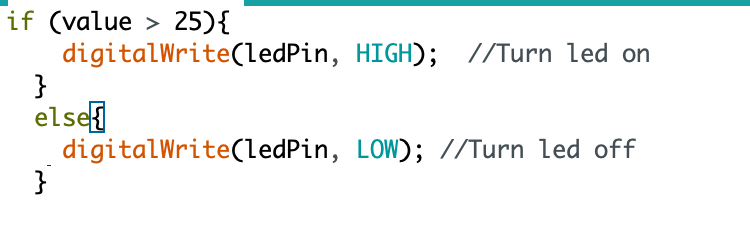
A quick google search yielded this page from Arduino. I initially thought it gave the arduino another option in light output, allowing for more “in-between” values (instead of digitalWrite HIGH & digitalWrite LOW). 

However, THIS guide summarized the map function as an analog/digital conversion- “The map function is intended to change one range of values into another range of values and a common use is to read an analogue input (10 bits long, so values range from 0 to 1023) and change the output to a byte so the output would be from 0 to 255.”

So, from my understanding, the analog input (the photoresistor) would send the arduino values, but the code would convert the range of values into something with a greater span, so an easier transition could be had from a brighter to a dimmer output. While it wasn’t exactly what I was thinking it would do, this was cool because it gave me the option to make the light for my final sloooooowly turn on as the sun set, as opposed to a harsh on/off when the read values from the photoresistor fell or rose above a specified value. 

However, with that in mind, I knew this would be rough to implement because coding isn’t exactly my strong suit. I wasn’t able to get it to work as planned, but this was the code I thought would work best. 
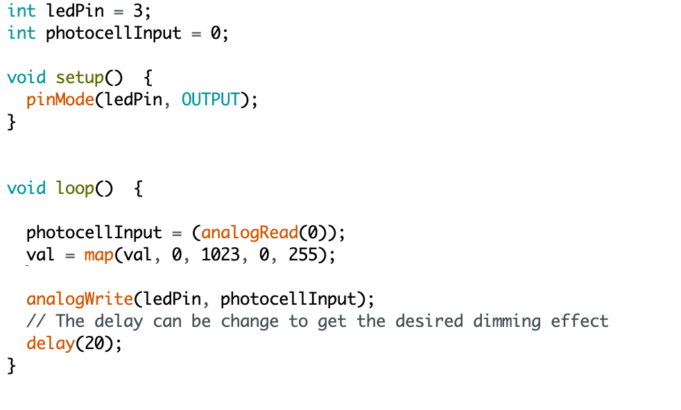

While I wasn’t able to get any of the other assignment features complete (integrate a potentiometer or a second component in general), I’m happy I have a better understanding of the analog side of the arduino! 

Simple Circuit Experimentation


So I was actually able to work out the first part of this assignment (the Basic Switch) when I was working on my final project. The setup and guide was extremely straightforward, no issues whatsoever. While I don’t have any picture proof (I immediately went from the button to utilizing a photoresistor and soon swapped out the light for a relay modulated grow light), I want to talk about the code I briefly used. 


When playing with the setup, I knew that it would be easy to switch out the button for a photoresistor. I also knew that I’d have to make the light turn ON when the photoresistor was covered, so this was a nice start to also messing with the code I’d later use.

I didn’t change the base code from the guide at all-  

The next step was to switch gears and work on working with a photoresistor. Perfect. The guide gave a nice rundown on how the circuit works, which was perfect when transitioning into the final. I built everything and ran it according to the code provided, but switched the digital write functions to provide light when the photoresistor was covered, as to mimic what I’d be doing on the final; 


Overall, I thought this was a fun, easy, and relatively straightforward project to crank out. It was a nice “starting” project before I dove into working with more complex circuits for the final, and I’m happy the circuits and explanations were easy to run through. 

Processing Experimentation

Creating a Color Gradient


For my experiment, I wanted to change the values of in the Processing example CreateImage, where you are given a buffer of pixels to mess with. The example itself shows a blue gradient that transitions from blue into the background, and is off center. In my experiment, I made everything centered, made the size of the window square, made the image itself smaller, and changed the gradient to go from a bright red to a navy blue.


PImage img;


void setup() {

size(640, 640);

img = createImage(100, 100, ARGB);

for(int i = 0; i < img.pixels.length; i++) {

float a = map(i, 0, img.pixels.length, 255, 0);

img.pixels[i] = color(a, 10, 45, 200);

}

}


void draw() {

background(0);

image(img, 280, 280);

image(img, mouseX-img.width/2, mouseY-img.height/2);

}

Analog Output Experimentation


Analog Output Experimentation (Photoresistor + Joystick Attempt)
Following the Arduino tutorial, I successfully set up the photoresistor and used it to control the blinking of an LED.


Following this tutorial, I successfully set up a circuit for using the joystick to control the LED lights blinking on and off. My next step was to integrate the above photoresistor into this circuit so that I could cause the LEDS to blink in different ways (such as blinking in rapid succession when dark and blinking once normally when light) depending on the ambient light values detected.

However, I had trouble getting this to execute properly.

Circuit
In addition to the joystick circuit, I had the photoresistor connected to analog pin 2 with a 220 ohm resistor.


Code Attempt
I made minor changes to the left-right controlling code to test out whether the photoresistor integration would work or not. If the ambient light levels fell below 450 while the joystick was being pushed to the left, then the LED should blink in rapid succession. If the joystick was pushed to the left with the light levels above 450, then it should blink once normally. If the joystick was not pushed to the left, then the LED would remain off. The result of this circuit and code was that there was no change. I don't see where the problem is now, but I'll continue to investigate. Hopefully I didn't overlook some silly mistake!

int UD = 0;
int LR = 0;
const int sensorPin = A2;
/* Arduino Micro output pins*/
int DWN = 13;
int UP = 12;
int LEFT = 11;
int RT = 10;
/*Arduino Micro Input Pins */
int IUP=A0;
int ILR=A1;
int MID = 10; 
int LRMID = 0;
int UPMID = 0;

void setup(){
  pinMode(DWN, OUTPUT);
  pinMode(UP, OUTPUT);
  pinMode(LEFT, OUTPUT);
  pinMode(RT, OUTPUT);
  digitalWrite(DWN, HIGH);
  digitalWrite(UP, HIGH);
  digitalWrite(LEFT, HIGH);
  digitalWrite(RT, HIGH);

//calibrate center

  LRMID = analogRead(ILR);
  UPMID = analogRead(IUP); 
  
}

void loop(){
  int sensorReading = analogRead(A2);
  UD = analogRead(IUP);
  LR = analogRead(ILR);

// UP-DOWN

  if(UD < UPMID - MID){
    digitalWrite(DWN, HIGH);   
  } else {
    digitalWrite(DWN, LOW);
}

  if(UD > UPMID + MID){
    digitalWrite(UP, HIGH); 
} else {
  digitalWrite(UP, LOW);
} 


// LEFT-RIGHT

if(LR < LRMID - MID){
  digitalWrite(LEFT, HIGH);
} else {
  digitalWrite(LEFT, LOW);
}

if(LR > LRMID + MID && sensorReading <= 450){
  digitalWrite(RT, HIGH);
  delay(200);
  digitalWrite(RT, LOW);
  delay(200);
} else if (LR > LRMID + MID) {
  digitalWrite(RT, HIGH);
} else {
  digitalWrite(RT, LOW);
}

delay(400);

}


Capsense Library Exploration


Capacitive Sensor
Following the Youtube and Instructables tutorials, I was able to successfully set up the capacitive sensor.


I then tried to follow this tutorial to use the capacitive sensor to control the blinking of an LED, but I ran into the issue where the LED would only stay lit up rather than blink in response to touch. I did not know how to solve this issue, as the circuit and code appeared correct. I suspect that the issue had to do with the sensitivity of the capacitive sensor, but I will continue to investigate.


Processing Experimentation : Mixture Grid


1.
/**
* Mixture Grid
* modified from an example by Simon Greenwold.
*
* Display a 2D grid of boxes with three different kinds of lights.
*/
void setup() {
size(1440, 900, P3D);
noStroke();
}
void draw() {
defineLights();
background(0);

for (int x = 0; x <= width; x += 60) {
for (int y = 0; y <= height; y += 60) {
pushMatrix();
translate(x, y);
rotateY(map(mouseX, 0, width, 0, PI));
rotateX(map(mouseY, 0, height, 0, PI));
box(120,15,45);
sphere(12);
popMatrix();
}
}
}
void defineLights() {
// Green point light on the right
pointLight(51, 255, 0, // Color
300, -100, 0); // Position
// Purple directional light
directionalLight(130, 67, 255, // Color
1, 0, 0); // The x-, y-, z-axis direction
// Blue spotlight from the front
spotLight(58, 216, 255, // Color
0, 40, 200, // Position
1, 3, -0.5, // Direction
PI / 2, 2); // Angle, concentration
}
2. Lights on Rotating Shapes and Changing Colors
3.  I changed variables that are parts of the initial code already.  First of all, I changed the size of the artboard and the boxes that are respondent to the cursor. Also, I added another sphere shape to each grid. After that, I modified the colors of shapes and shades to make it cooler! 

Voltage Divider Experimentation


Voltage Divider
At first, I ran into the problem of the LED not lighting up, even though the circuit connections were all correct. After double checking my code, I realized that it was simply an issue of my unique lighting set up, and quickly changed the parameter value in the code based on the light intensity levels of my room as reported by the serial monitor.


Blink Speed Change
After successfully using the circuit to change the brightness of the LED, I tried to then use it to change the blink speed so that the darker it was, the faster the LED would blink.

Code
const int ledPin=9;
const int sensorPin = A0;

void setup() {
// initialize serial communications (for debugging only):
Serial.begin(9600);
pinMode(ledPin, OUTPUT);
pinMode(sensorPin,INPUT);
}

void loop() {
// read the sensor:
int sensorReading = analogRead(A0);
// print the sensor reading so you know its range
Serial.println(sensorReading);
// map the analog input range
// to the output LED range

if (sensorReading <= 450) {
  digitalWrite(ledPin, HIGH);
  delay(200);
  digitalWrite(ledPin, LOW);
  delay(200);
} else {
  // change blink speed:
  digitalWrite(ledPin, HIGH);
  delay(1000);
  digitalWrite(ledPin, LOW);
  delay(1000);
}
}

Circuit
The circuit was the same for both experiments.