As computing becomes more ubiquitous in our objects, designers need to be more aware of how to design meaningful interactions into electronically enhanced objects. At the University of Washington, a class of junior Interaction Design majors is exploring this question. These pages chronicle their efforts.

Friday, June 12, 2020

Final Prank Documentation

Surprise Tickle Prank
I decided to try to use Arduino to surprise tickle people when they sit at their desk. How diabolical!

Circuit
I had a couple of ideas for how to sense the pranked person when they sat at their desk, such as light fluctuations and motion detection, but eventually I settled on using light for simplicity's sake. Thus, I began this project by setting up the servo motor and then integrating the photoresistor into the circuit.


Initial Code

#include <Servo.h>

Servo servo1;

void setup() {

  // set the servo pin, pin 9, as a servo output pin
  servo1.attach(9);
}

void loop() {
  //Read the light value from the photoresistor
  int lightValue = analogRead(A0);

  // map the light readings to the angle possible by the servo motor
  lightValue = map (lightValue, 0, 1023, 0, 180);

  // control the servo motor based on the light value read, adjust linearly by angles
  servo1.write(lightValue);

}


Progress!
I was able to successfully use the light values detected by the photoresistor to determine the angle of the servo rotation.


Refinement
I realized that to simulate tickling, the movement of the servo had to be erratic rather than simple and fixed like the above motions (which were determined by the detected light values). Thus, I had to simplify the code further and use the photoresistor solely to determine whether the light detected had dropped below a specified value (instead of reporting back each value). If the photoresistor detected darkness (a person sitting in front of the resistor, blocking light), then the Arduino would actuate servo rotation of a random value until the person got up from the seat (allowed light to be detected again).


In the above video, I taped a bundle of fluffed up q-tips to the servo since I didn't have feathers, but ideally one would use feathers for tickling. I also did not have the means to put together the whole prank set up, but I have included a diagram of what it would look like below. The servo and feathers would have to be positioned in a spot that is inconspicuous but also open enough to easily reach the pranked person. This would likely be at the bottom of the desk leg. Additionally, I would tape a paper towel roll to the photoresistor to point it at where the pranked person would sit so that it would not be affected by nearby light changes. 


Refined Code
#include <Servo.h>

Servo servo1;

void setup() {
  // put your setup code here, to run once:
  Serial.begin(9600);
  // set the servo pin, pin 9, as a servo output pin
  servo1.attach(9);
}

void loop() {
  //Read the light value from the photoresistor
  int lightValue = analogRead(A0);
  Serial.println(lightValue);
  // map the light readings to the angle possible by the servo motor
  // lightValue = map (lightValue, 0, 1023, 0, 180);
  
  if (lightValue < 500) {
    servo1.write(random(30, 360));
    delay(random(10,300));
  }

}


Next Steps?
Rather than using the photoresistor to detect when someone has sat down at their desk, it would be more effective to use a capacitive touch sensor that can discern a person's proximity to the desk. That way, the set up would be unaffected by uncontrolled variables such as ambient light changes due to the time of day. To use the capacitive touch sensor, though, I would have to make sure that the pranked person touched the sensor material in some way. Perhaps I could put a discrete piece of aluminum foil on the desk chair..? This is something that I would look into if I was to continue developing this project.

Thanks for reading!


Analog Output Experimentation

In this project, I used the photoresistor and buzzer to make a buzzer that would interact with the photoresistor and button.

BREADBOARD:


CODE:
The code is very simple and just takes the reading of the photosensor and maps that as the pitch for the buzzer. When the button is pressed the buzzer will sound at the frequency based on the photoresistor.

int buttonPin = 2;

void setup() {
  // initialize serial communications (for debugging only):
  Serial.begin(9600);
}

void loop() {
  // read the sensor:
  int sensorReading = analogRead(A0);
  // print the sensor reading so you know its range
  Serial.println(sensorReading);
  // map the analog input range (in this case, 400 - 1000 from the photoresistor)
  // to the output pitch range (120 - 1500Hz)
  // change the minimum and maximum input numbers below depending on the range
  // your sensor's giving:
  int thisPitch = map(sensorReading, 0, 500, 120, 1500);

  // play the pitch:
  if (digitalRead(buttonPin)){
    tone(9, thisPitch, 10);
    delay(1);        // delay in between reads for stability
  }
}

Take Apart Project


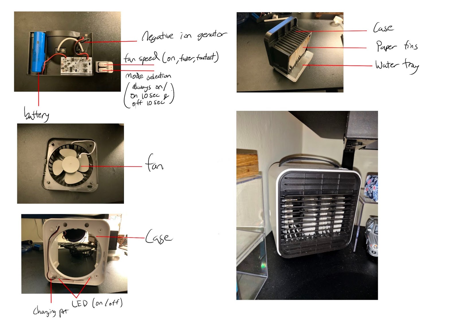
In this project, I decided to take apart my desk "AC" fan. This fan has a water/ice tray that can be used to cool down the air of the fan to give an airconditioning affect. This fan is very simple with a battery and small board to adjust fan speed and intermittent fan mode. It also has a few LED to indicate battery charge and the fan speed/mode. There is also a negative ion generator which does not seem to do much, but apparently can release negative ions that go into the air to attach to positively charged particles like dust, smoke or other allergens that would then dissipate from the air in your room.

This fan simply takes input from the fan speed to turn on and from there you can adjust the mode. Once the button is pressed the signal will be sent to the fan module to start spinning its motor. If the mode is pressed it will then intermittently turn off and on every 10 seconds. Indicator lights will also turn on when each button is pressed to give feedback to the user.

Simple Circuit Experimentation

In this project, I use 2 LED's and a photoresistor to make a simple circuit that mimics cop light patterns. When there is more light present to the photoresistor the lights flash quicker.

BREADBOARD:

CODE:
The method I used to get the photoresistor to change the speed of the flashes was to make the blinkDelay variable map the light value within a specific range. When the light is mapped it can be fine-tuned to the correct range of blinkDelay values you want.
The only issue I found was that the blinks would not gradually get faster, but it would quickly change its blink delay after it went through a cycle. So in essence, when a light is flashed on the photoresistor it would finish its cycle then update to the shorter blink delay.
This can be seen in the video above.

//Constants
const int pResistor = A0; // Photoresistor at Arduino analog pin A0

//Variables
int LED1 = 8;
int LED2 = 12;
int blinkDelay;
int lightVal;

// the setup function runs once when you press reset or power the board
void setup() {
  // initialize digital pin LED_BUILTIN as an output.
  pinMode(LED1, OUTPUT);
  pinMode(LED2, OUTPUT);
  Serial.begin(9600);
}

// the loop function runs over and over again forever
void loop() {
  lightVal = analogRead(pResistor);
  blinkDelay = map(lightVal, 200, 700, 400, 100);
  Serial.println(lightVal);
    for(int x = 0; x < 2; x++) {
      digitalWrite(LED1, HIGH);   // turn the LED on (HIGH is the voltage level)
      delay(blinkDelay);
      digitalWrite(LED1, LOW);
      delay(blinkDelay);
    }
    delay (blinkDelay);
    for(int x = 0; x < 2; x++) {
      digitalWrite(LED2, HIGH);
      delay(blinkDelay);                       // wait for a second
      digitalWrite(LED2, LOW);    // turn the LED off by making the voltage LOW
      delay(blinkDelay);                       // wait for a second
    }
  }

Final Project (automatic fridge closer)

In this project, I use the photoresistor, stepper motor, LED, and buzzer to make a self-closing fridge. The goal of this project is to make something that detects when the fridge is open for X amount of time and closes it after that time.

BREADBOARD:

HOW IT WORKS:
This video has a 5 second delay not a 5 minute delay for the purposes of testing and shooting this video***

CODE:
I started writing this code being able to detect when the fridge is open. When the fridge is open the light inside the fridge is on. I used the photoresistor to detect when the light is on and would wait 5 minutes before blinking its LED and buzzing for a couple seconds. After it would begin moving the motor to close the fridge.
I ran into issues with the mechanism knowing when to turn off and reset. I had a few variables that would hold its value after the fridge being closed. Meaning it would remember it already waited 5 minutes. In order to fix this issue, I had to reset the variable LEDcount back to zero after every time the motor moved. Also when the photoresistor was receiving zero light value the same variable would reset to 0 so no residual counts would be held after a cycle has gone by.

#include <Stepper.h>

// Conncetions
const int pResistor = A0; // Photoresistor at Arduino analog pin A0
int LED = 2;
int BUZZER = 3;

// Variables
int lightVal;
float checkTime = 0;
bool ledState = 0;
int ledCount = 0;
int buzzCount = 0;

// Stepper motor variables
const float STEPS_PER_REV = 32;
const float GEAR_REDUCTION = 64;
const float STEPS_PER_OUTPUT_REV = STEPS_PER_REV * GEAR_REDUCTION;
int StepsReq;
Stepper steppermotor(STEPS_PER_REV, 8, 10, 9, 11);

void setup() {
  pinMode(LED, OUTPUT);
  Serial.begin(9600);
  checkTime = millis();
}

void loop() {
  lightVal = analogRead(pResistor);
  Serial.println(lightVal);

  if (lightVal >= 200) {                              // if the fridge light is on then...
    if (millis() - checkTime >= 100) {                // blink led
      ledState = ! ledState;
      digitalWrite(LED, ledState);
      checkTime = millis();
      ledCount++;
    }
    if (ledCount >= 3000) {                             // if the LED has been on for 5 minutes (3000 counts = 300000ms = 5 min) then...
      buzzCount = 0;
      while (buzzCount < 500) {
        tone(BUZZER, 100, 100);                       // play tone
        delay(1);                                     // delay in between reads for stability
        buzzCount++;
      }

      delay(2000);                                    // delay before closing fride
   
      StepsReq = STEPS_PER_OUTPUT_REV / 2;            // Make the motor turn CW 180 degrees
      steppermotor.setSpeed(700);
      steppermotor.step(StepsReq);
      delay(4000);                                    // delay before resetting closing arm

      StepsReq = - STEPS_PER_OUTPUT_REV / 2;          // the minus makes it turn the other way
      steppermotor.setSpeed(700);
      steppermotor.step(StepsReq);
      delay(4000);                                    // delay before it resets and checks if the fridge remains open
   
      digitalWrite (LED, 0);                          // turn the led off so the light turns back on in the next loop (DOESNT WORK!!!)
    }
  }
  else {
    ledCount = 0;                                     // resetting variables incase fridge is closed before it counts up
    digitalWrite (LED, 0);
  }
}

ISSUES:
I was unable to get a material to attach to the end of my stepper motor to actually physically move the fridge closed. I, unfortunately, did not have the materials or tools to build the proper arm without it coming off or falling apart. Due to this, my project was unsuccessful in its final result. However,
I learned a lot in building and troubleshooting details within my code and physically wiring. I believe if I were to 3D print the proper arm, this project would be feasible.

Voltage Divider Experimentation

For this project, while setting up the circuit I ran into an issue of my LED not lighting up. After double checking the resistors and removing the LDR to learn that the LED was lighting up properly, (like Lily) I learned that the code itself needed to be changed to reflect my lighting situation. I also thought the value of the LDR being 25 seemed really low after realizing this.


After that was fixed, I changed the code so that the LED would blink in a loop unless the value of the LDR was less than 400, in which case it would turn off. Through this experimentation is how I was inspired to create an alarm that alerts me when my cat is on the counter.


//Constants
const int pResistor = A0; // Photoresistor at Arduino analog pin A0
const int ledPin=9;       // Led pin at Arduino pin 9

//Variables
int value;          // Store value from photoresistor (0-1023)

void setup(){
 pinMode(ledPin, OUTPUT);  // Set lepPin - 9 pin as an output
 pinMode(pResistor, INPUT);// Set pResistor - A0 pin as an input (optional)
}

void loop(){
  value = analogRead(pResistor);
 
  if (value >= 400){
    digitalWrite(ledPin, LOW);
    delay(100);
    digitalWrite(ledPin, HIGH);
    delay(100);
   
  }
  else{
    digitalWrite(ledPin, LOW); //Turn led off
  }

}

Basic Switch Experimentation

I referenced the Arduino tutorial on how to use a button switch to light up my LED.

I ran into an issue where the LED wouldn't turn on, but I knew that the button was working based on the status of the Arduino itself. After checking that the resistors were correct and moving wires around, I realized that one of my wires connecting the LED to ground had broken off in the Arduino itself. After replacing that wire, everything went much more smoothly.


Goodbye, yellow wire