As computing becomes more ubiquitous in our objects, designers need to be more aware of how to design meaningful interactions into electronically enhanced objects. At the University of Washington, a class of junior Interaction Design majors is exploring this question. These pages chronicle their efforts.

Monday, May 6, 2013

Nick/Mason ~ Readin 'Duinos


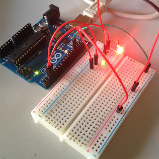
This week Nick and I taught our Arduino to read values from a Text file (.txt) to blink LEDs Processing reads the text file in real time, only sending new information to the Arduino. Later we will implement live updating text from a weather source that gives the Arduino weather interpreting capabilities.


The Processing code used is shown below:
import processing.serial.*;
import java.io.*;
int mySwitch=0;
int counter=0;
String [] subtext;
Serial myPort;
void setup(){
//Create a switch that will control the frequency of text file reads.//When mySwitch=1, the program is setup to read the text file.//This is turned off when mySwitch = 0 mySwitch=1;
//Open the serial port for communication with the Arduino//Make sure the COM port is correct myPort = new Serial(this, "COM6", 9600);
myPort.bufferUntil('\n');
}
void draw() {
if (mySwitch>0){
/*The readData function can be found later in the code. This is the call to read a CSV file on the computer hard-drive. */ readData("Users/Nick/SensorData.txt");
/*The following switch prevents continuous reading of the text file, until we are ready to read the file again. */ mySwitch=0;
}
/*Only send new data. This IF statement will allow new data to be sent to the arduino. */if(counter<subtext.length){
/* Write the next number to the Serial port and send it to the Arduino There will be a delay of half a second before the command is sent to turn the LED off : myPort.write('0'); */ myPort.write(subtext[counter]);
delay(500);
myPort.write('0');
delay(100);
//Increment the counter so that the next number is sent to the arduino. counter++;
} else{
//If the text file has run out of numbers, then read the text file again in 5 seconds. delay(5000);
mySwitch=1;
}
}
/* The following function will read from a CSV or TXT file */void readData(String myFileName){
File file=new File(myFileName);
BufferedReader br=null;
try{
br=new BufferedReader(new FileReader(file));
String text=null;
/* keep reading each line until you get to the end of the file */while((text=br.readLine())!=null){
/* Spilt each line up into bits and pieces using a comma as a separator */ subtext = splitTokens(text,",");
}
}catch(FileNotFoundException e){
e.printStackTrace();
}catch(IOException e){
e.printStackTrace();
}finally{
try {
if (br != null){
br.close();
}
} catch (IOException e) {
e.printStackTrace();
}
}
}

Thursday, May 2, 2013

Enrique & Karin - Week 4

We received our first sensor in the mail late last week. It reads the moisture levels in the soil. This week we wanted to test the sensor by having it detect the water in the soil and provide an analog output.

First we connected three different colored lights to the circuit board. Then we established numerical values for "dry", "moist", and "wet". Lastly we wrote the code that would take the moisture readings and prompt the correlating light to turn on and the one before it to turn off.

Below is a video of what our test looked like:

And this is the code that made it possible:


/*
  # Experiment code for the moisture sensor
  # Editor     : Karin & Enrique
  # Date       : 05.02.2013
  # Version    : 1.0
  # Connect the sensor to the A0(Analog 0) pin on the Arduino board
  # Connect LEDs to pin 13, 8 & 7
  # Give the sensor 5V input

  # the sensor value description
  # 0  ~500     in water
  # 500~700     humid soil
  # 700~1000     dry soil
*/

int green = 13;
int yellow = 8;
int red = 7;

int moistureValue = 0;

void setup(){
  // initialize the digital pins as outputs.
  pinMode(green, OUTPUT);
  pinMode(yellow, OUTPUT);
  pinMode(red, OUTPUT);

  Serial.begin(9600);
 }

void loop(){
  moistureValue = analogRead(0);
  Serial.print("Moisture Sensor Value: ");
  Serial.println(moistureValue, DEC);
  delay(100);

  //Light red if it's dry
  if (moistureValue >700){
     digitalWrite(red, HIGH);   // turn the LED on (HIGH is the voltage level)
     digitalWrite(yellow, LOW);   // turn the other LEDs off
     digitalWrite(green, LOW);
  }
  //Light green if it's really wet
  else if(moistureValue < 500){
     digitalWrite(green, HIGH);   // turn the LED on (HIGH is the voltage level)
     digitalWrite(yellow, LOW);  // turn the other LEDs off
     digitalWrite(red, LOW);
  }
  //Light Yellow if it's moist
  else{
    digitalWrite(yellow, HIGH);   // turn the LED on (HIGH is the voltage level)
    digitalWrite(red, LOW);   // turn the other LEDs off
    digitalWrite(green, LOW);
  }

}

Tuesday, April 30, 2013

5 Blinks Counting | Sam + Willie

So. Willie and made the Arduino blink. But not just blink. Blink and count up from 1 to 5, then start again.
So,

Blink.
Then Blink Blink.
Then Blink Blink Blink, etc.
Dig?

We got a little hung up with the nested for loops, but with a little help from our friends, we made it happen.

---

Here's the code:


// blink counting from 1 blink to 5

int counter = 0;  // a counter for using with my blinking loop
int led = 13;     // the led pin

void setup() {
  pinMode(led, OUTPUT);
}

// my blink function
void blink(int g) {
  for (int x = 0; x <= g; x++) {
    digitalWrite(led, HIGH);
    delay(500);
    digitalWrite(led, LOW);
    delay(200);
  }
}

// my loop!
void loop() {
  for (int counter = 0; counter < 5; counter++) {
    blink(counter);
    delay(800);
  }
}


The GIFt of Light

SAM: William ... come see thine latest creation

WILLIE: Ser Samuel what discovery of wonder and creation of magic hath you delivered here today?!

S: It ish a curcuit my simple friend. One that uses both the simple LED circuitry I have shown you previously and a three-post variable potentiometer -- a dial, Ser William -- to control the brightness of said light.

W: fffaassssssccinating Samuel

S: But there is more! As I control this system and output feed is transfered back to my computer operating system, displaying to me the changes in intensity  and resistance of energy.

W: I am frozen in a state of amazement! 

-------------------------------------

Below is a GIF of 
a) the process in motion 
b) sam represents what the LED is doing
c) willie represents what the dial is doing to control the LED
d) a gif of hands to represent the motion of electrons in our circuit


Our Code looks like this:

/*
  Analog input, analog output, serial output

 Reads an analog input pin, maps the result to a range from 0 to 255
 and uses the result to set the pulsewidth modulation (PWM) of an output pin.
 Also prints the results to the serial monitor.

 The circuit:
 * potentiometer connected to analog pin 0.
   Center pin of the potentiometer goes to the analog pin.
   side pins of the potentiometer go to +5V and ground
 * LED connected from digital pin 9 to ground

 created 29 Dec. 2008
 modified 9 Apr 2012
 by Tom Igoe

 This example code is in the public domain.

 */

// These constants won't change.  They're used to give names
// to the pins used:
const int analogInPin = A0;  // Analog input pin that the potentiometer is attached to
const int analogOutPin = 9; // Analog output pin that the LED is attached to

int sensorValue = 0;        // value read from the pot
int outputValue = 0;        // value output to the PWM (analog out)

void setup() {
  // initialize serial communications at 9600 bps:
  Serial.begin(9600); 
}

void loop() {
  // read the analog in value:
  sensorValue = analogRead(analogInPin);            
  // map it to the range of the analog out:
  outputValue = map(sensorValue, 0, 1023, 0, 255);  
  // change the analog out value:
  analogWrite(analogOutPin, outputValue);           

  // print the results to the serial monitor:
  Serial.print("sensor = " );                       
  Serial.print(sensorValue);      
  Serial.print("\t output = ");      
  Serial.println(outputValue);   

  // wait 2 milliseconds before the next loop
  // for the analog-to-digital converter to settle
  // after the last reading:
  delay(2);                     
}


Monday, April 29, 2013

AnalogRead Serial.print and light sensors


For this portion I was taking the components we were looking at in class and adding elements of the serial reading and printing in order to get a sense of what was going on behind the scenes. Did run into a problem where the data was scrolling side ways but it turned out that I needed to add a Serial.println(); which would start a new line.

Being able to see the read out helped me adjust the value so I got the best range for the LED which was One fourth of the analog readout.


code below


/*
  Blink
 Turns on an LED on for one second, then off for one second, repeatedly.

 This example code is in the public domain.
 */
// Pin 13 has an LED connected on most Arduino boards.
// give it a name:
int sensorPin = A0;
int ledPin = 9;
int sensorValue = 0;
// the setup routine runs once when you press reset:
void setup() {              
  // initialize the digital pin as an output.
  pinMode(ledPin, OUTPUT);
  Serial.begin(9600); // starts communication with computer
}
// the loop routine runs over and over again forever:
void loop() {
  sensorValue = analogRead(sensorPin);
  analogWrite(ledPin, sensorValue/4 );
  Serial.print("sensor = " );                     
  Serial.print(sensorValue/4);    
  Serial.println();

}

5 Blink ~ Nick Stoermer


Five blink sequence

For the brute force it was pretty straight forward groups of on/off separated by delays. For the more effective method I ended up using encapsulation to have a blink function which I could then pass a variable which would define how many time it blinked. I then put this inside a for loop which controlled the variable that was passed. I realized that this project could have been done with  just nested for loops but for the purpose of learning the building blocks of Arduino this was more important. 

code below

~~~~~~~~~~~


/*
  Blink
 Turns on an LED on for one second, then off for one second, repeatedly.

 This example code is in the public domain.
 */

// Pin 13 has an LED connected on most Arduino boards.
// give it a name:
int led = 13;

// the setup routine runs once when you press reset:
void setup() {                
  // initialize the digital pin as an output.
  pinMode(led, OUTPUT);     
}

// the loop routine runs over and over again forever:
void loop() {
  //1
  digitalWrite(led, HIGH);   // turn the LED on (HIGH is the voltage level)
  delay(300);               
  digitalWrite(led, LOW);    // turn the LED off by making the voltage LOW
  delay(300);  

  delay(1000)                 // 1 sec pause for inbetween


    //2
    digitalWrite(led, HIGH);   
  delay(300);               
  digitalWrite(led, LOW);    // turn the LED off by making the voltage LOW
  delay(300);  

  digitalWrite(led, HIGH);   // turn the LED on (HIGH is the voltage level)
  delay(300);               
  digitalWrite(led, LOW);    // turn the LED off by making the voltage LOW
  delay(300);  

  delay(1000)                 // 1 sec pause for inbetween


    //3
    digitalWrite(led, HIGH);   // turn the LED on (HIGH is the voltage level)
  delay(300);               
  digitalWrite(led, LOW);    // turn the LED off by making the voltage LOW
  delay(300);  

  digitalWrite(led, HIGH);   // turn the LED on (HIGH is the voltage level)
  delay(300);               
  digitalWrite(led, LOW);    // turn the LED off by making the voltage LOW
  delay(300);  

  digitalWrite(led, HIGH);   // turn the LED on (HIGH is the voltage level)
  delay(300);               
  digitalWrite(led, LOW);    // turn the LED off by making the voltage LOW
  delay(300);  

  delay(1000)                 // 1 sec pause for inbetween


    //4
    digitalWrite(led, HIGH);   // turn the LED on (HIGH is the voltage level)
  delay(300);               
  digitalWrite(led, LOW);    // turn the LED off by making the voltage LOW
  delay(300);  

  digitalWrite(led, HIGH);   // turn the LED on (HIGH is the voltage level)
  delay(300);               
  digitalWrite(led, LOW);    // turn the LED off by making the voltage LOW
  delay(300);  

  digitalWrite(led, HIGH);   // turn the LED on (HIGH is the voltage level)
  delay(300);               
  digitalWrite(led, LOW);    // turn the LED off by making the voltage LOW
  delay(300);  

  digitalWrite(led, HIGH);   // turn the LED on (HIGH is the voltage level)
  delay(300);               
  digitalWrite(led, LOW);    // turn the LED off by making the voltage LOW
  delay(300);  

  delay(1000)                 // 1 sec pause for inbetween


    //5

    digitalWrite(led, HIGH);   // turn the LED on (HIGH is the voltage level)
  delay(300);               
  digitalWrite(led, LOW);    // turn the LED off by making the voltage LOW
  delay(300);  

  digitalWrite(led, HIGH);   // turn the LED on (HIGH is the voltage level)
  delay(300);               
  digitalWrite(led, LOW);    // turn the LED off by making the voltage LOW
  delay(300);  

  digitalWrite(led, HIGH);   // turn the LED on (HIGH is the voltage level)
  delay(300);               
  digitalWrite(led, LOW);    // turn the LED off by making the voltage LOW
  delay(300);  

  digitalWrite(led, HIGH);   // turn the LED on (HIGH is the voltage level)
  delay(300);               
  digitalWrite(led, LOW);    // turn the LED off by making the voltage LOW
  delay(300);  

  digitalWrite(led, HIGH);   // turn the LED on (HIGH is the voltage level)
  delay(300);               
  digitalWrite(led, LOW);    // turn the LED off by making the voltage LOW
  delay(300);  

  delay(1000)                 // 1 sec pause for inbetween


    // wait for a second

  }


Pressure Sensors & Amy's Ego...

Pressure Sensor:
Our sensor was a paper thin strip with a circle pad that was a pressure sensor. The harder you squeeze the brighter the bulb got, but it never turned all the way off upon release.
int sensorPin = A0;int ledPin = 9;int sensorValue = 0;
void setup(){ pinMode(ledPin, OUTPUT);}
void loop() { sensorValue = analogRead(sensorPin); sensorValue = sensorValue/3; analogWrite(ledPin, sensorValue); //delay();}


Analog In/Out Serial: "Amy is ____ Beautiful"
*/
// the pins used:
const int analogInPin = A0; // Analog input pin that the potentiometer is attached to
const int analogOutPin = 9; // Analog output pin that the LED is attached to
int sensorValue = 0; // value read from the pot
int outputValue = 0; // value output to the PWM (analog out)
int count = 0;
void setup() {
// initialize serial communications at 9600 bps:
Serial.begin(9600);
}
void loop() {
count = count + 1;
// read the analog in value:
sensorValue = analogRead(analogInPin);
// map it to the range of the analog out:
outputValue = map(sensorValue, 0, 1023, 0, 255);
// change the analog out value:
analogWrite(analogOutPin, outputValue);
// print the results to the serial monitor:
//Serial.print("sensor = " );
//Serial.print(sensorValue);
//Serial.print("\t output = ");
Serial.print("Amy is");
Serial.print(count);
Serial.println( "x beautiful");
// wait 2 milliseconds before the next loop
// for the analog-to-digital converter to settle
// after the last reading:
delay(2);
}