
Friday, May 29, 2015
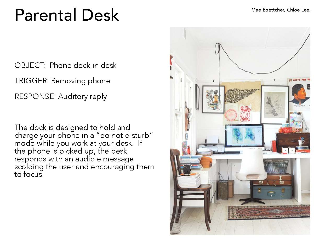
Parts//Mae and Chloe
We learned the hard way..order the correct parts ahead of time. And don't trust adafruit for $20 next day shipping.

Thursday, May 28, 2015
Soldering Adafruit//Mae and Chloe
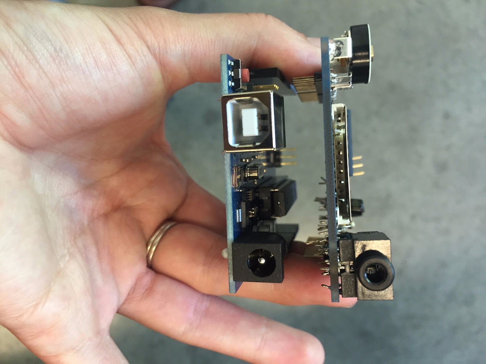
After we had a little bit of experience with the soldering while we were experimenting with the speakers, we felt like we were ready to put the adafruit wave shield together. Afterwards we realized there was a step by step manual on the adafruit website…. https://learn.adafruit.com/adafruit-wave-shield-audio-shield-for-arduino but thats besides the point! Learning is a beautiful thing….so is experimenting. Luckily we didn’t mess anything up too badly and at the end we figured it all out. What we found most challenging about the soldering was thinking ahead about attaching it to our existing arduino, and being thoughtful about which elements were attached to which side.

Speakers//Mae and Chloe
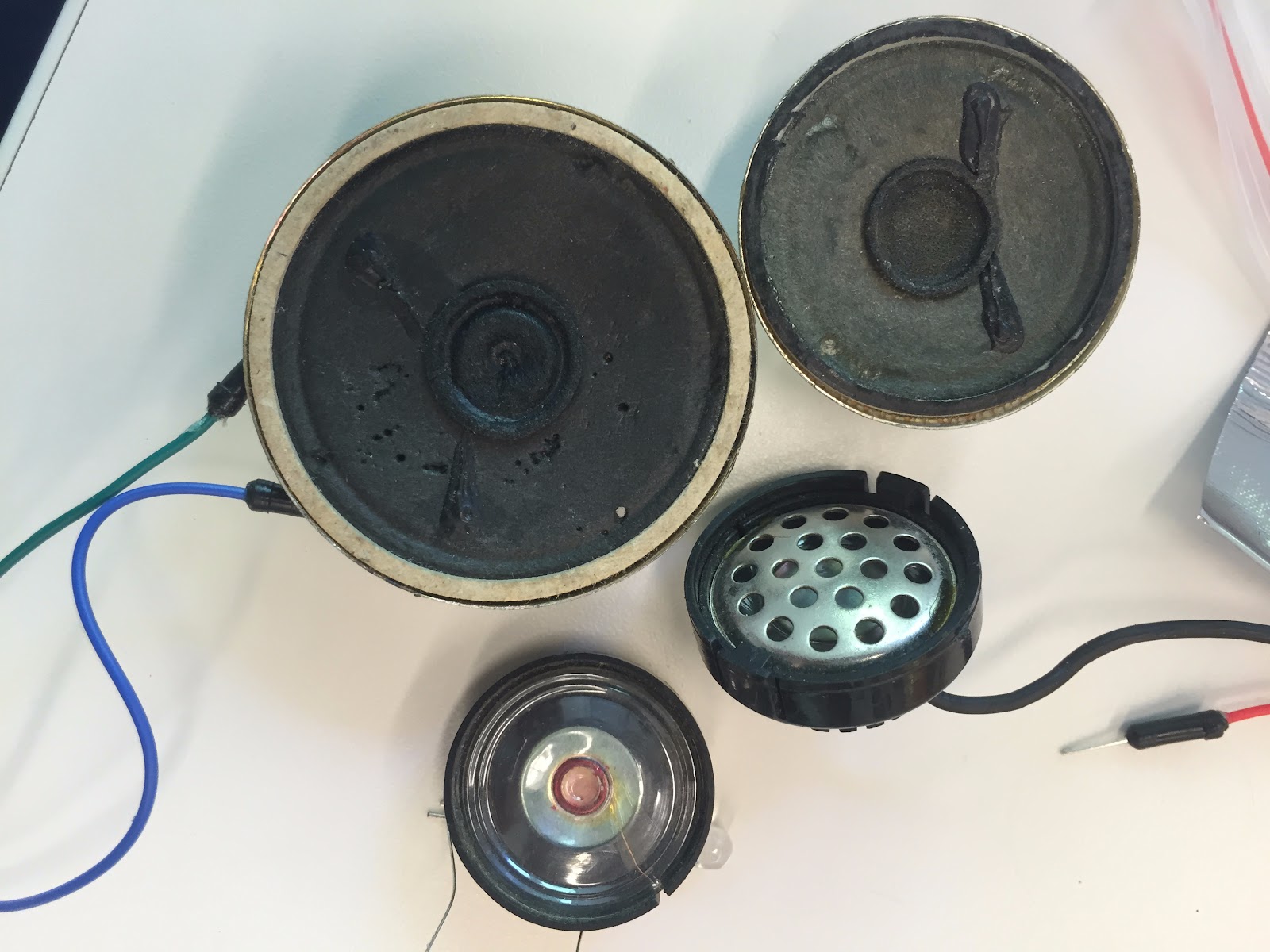
We tried using a used speaker to save some money, but after testing out a few we decided we needed to purchase a new one. We tried doing the “toneMelody” sketch to test the old ones, but unfortunately we couldn’t get any to work. We ended up ordering a speaker from the Adafruit website. The trouble shooting was at least a good opportunity to take our first stab at soldering.
Throughout all of this process we have been using the Adafruit website as a resource quite frequently. We have found tutorials, specifications, and much more that have all been valuable. Here we also learned about reformatting our SD card for the audio files we need.

Goodwill trip//Mae and Chloe
We went to the Goodwill to find a bedside table for our project. It ended up being more difficult that we thought. We had to take into account the purpose of our table when choosing which one we would use for our project. We decided on a table that had a front drawer (we’re exploring using the speaker as a knob.) The table we chose also has a small gap between the top and the drawer giving us a good place to hide the arduino.
Adafruit: ordering sensors//Mae and Chloe
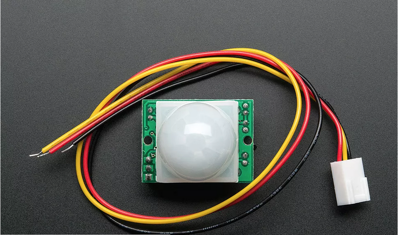
After we fully actualized what sensors we needed for this process, we began researching what specific components we needed to purchase. After a good amount of online exploring, we decided upon an Adafruit v1.1 Wave shield, and an Adafruit PIR motion sensor.

Which sensors? Which Actuators?//Mae and Chloe
We made this document to show how we imagined the motivational table interacting in a bedroom. We identified two sensors that we need to purchase and implement: the time sensor and the motion sensor. The motion sensor will be active between 7am and 9am, and will detect motion within the bedroom (presumably when someone is waking up.) From there, when the motion is detected, it will trigger the speaker playing the audio recording of motivational whispers to get people up and out of bed.

Motivational Pillow > Motivational Table//Mae and Chloe
At first we explored the idea of a motivational pillow that whispered sweet nothings. Unfortunately our idea was shot down as a pillow didn’t qualify as furniture. We were both still very stoked on the idea of waking up to sweet nothings so we explored other bedroom furniture. We decided to go with the bedside table because it would be easy to hide the arduino in a drawer and because it sits in a place that could easily detect motion.

Exploring Project Ideas//Mae and Chloe
We were instructed to do “research” about human interactions we surrounded ourselves with in everyday life for project ideas. So..naturally….we used a kegger as a good time to do some research. What we ended up with was actually ideas that were results of the kegger.
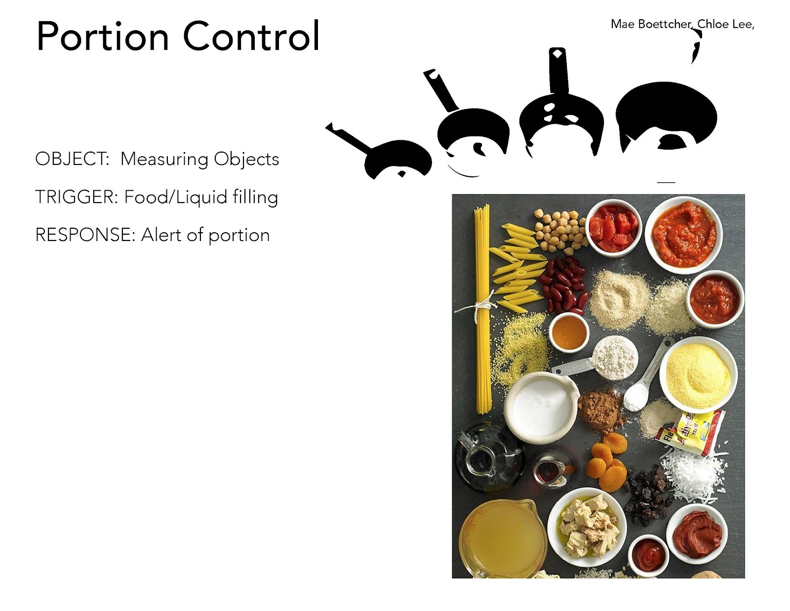
Idea #1 was drunchies. Everyone gets hungry when they’re drunk, how can we avoid out of control portions that make people feel like crap in the morning? Too much food makes people feel gross and get fat! We realized that this idea applies to not only drunchies, but every day life in how people consume food in general. So we investigated how we could design cookware to help provide portion control.
Idea #2 was hangover side effects. There are few things worse than trying to motivate yourself to get stuff done when you’re hungover. Another distracting factor in this process is cellphones. And college, you dont have a parent to tell you to get back to work. So how can a piece of furniture serve this purpose in college?
Idea #3 the morning after. The morning after a kegger, everyone needs a good cup of joe. And it sucks when that shit gets cold. What furniture can we make to enable people so stay on the couch with a warm cup of coffee?

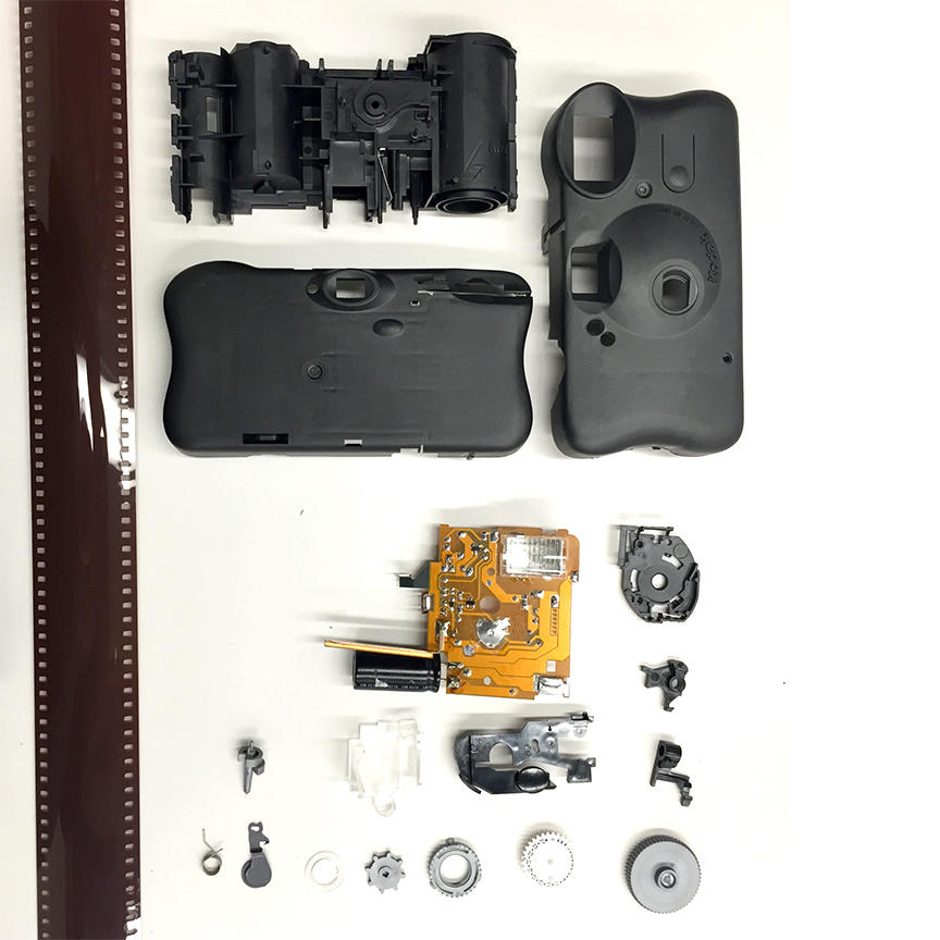
Disposable camera/Mae and Chloe


Sensor & Situation UPDATE // Gloria & Jessica
We moved forward with our Rain Lamp concept - but we decided to tweak it a little.
Rather than a rain lamp, it would be a weather lamp instead.
This is the way we imagine it working:
1) We will use processing to pull data/information from a weather server.
2) Then we'll connect processing with Arduino and make sure the Arduino is getting "commands" from processing.
3) We will code different patterns for the neopixel lights to react on the Arduino according to the weather forecast.
4) The neopixel lights will react based on weather conditions. (E.g. sunny = lights glow pink/orange/yellow, etc.)
Tuesday, May 26, 2015
Jordan & Tess pseudo code, actual code, set up, and chair
We have completed a basic set up of our arduino and code to simulate what our final project would be. First is the pseudo code which maps out our chair experience. Then we created the actual code which works so that when the photosensor is covered for 3 seconds a sound plays for 4 seconds. In our actual project the 3 seconds would be 1 hour (someone sitting) and the 4 seconds would be 5 minutes (someone taking a break). From here we have to complete our code to account for "if" statements. For example, if someone covered the photosensor for a half hour and then got up for a quick moment, we need to make sure the arduino doesn't reset itself.
Pseudo Code
if sit= false
{check light
set sit=true
}
if sit=true
start millis
check if millis>1hour
then beep for 3 mins
reset
Actual Code
boolean sit = false;
int photocellPin = 0;
int photocellReading;
int sitThreshold = 500;
int sitStart = 3000;
long sitLimit = 3000;
void setup() {
}
void loop() {
if (sit == false) {
photocellReading = analogRead(photocellPin);
if (photocellReading < sitThreshold) {
sit = true;
sitStart = millis();
}
}
if ((sit == true) && ((millis() - sitStart) > sitLimit)) {
tone(8, 300, 1000);
sit = false;
}
}
Arduino Set Up
We will have to find or soder longer wires in our final product to acommodate for the shape of the chair. We plan to place the photosensor on the seat of the chair and put the speaker on the back of the chair.

Chair!!
We realize that the aesthetics of this chair are not pleasing to the eye and therefor we will find some fun fabric to cover it with! The best thing about this chair is that it's extremely comfortable and spinny, definitely the kind of chair someone could spend over an hour in and need to be reminded to take a break.

Wednesday, May 20, 2015
No Phones At The Table – Pseudocode and Pseudotable – Rishi Agarwal and Annie Pyle
Pseudocode
In order to detect the presence of a phone at a two-person dining table, we will monitor a series of photoresistors. The photoresistors will be placed on the underside of the table and arranged as shown below.
Each person will be monitored by two photoresistors. Based on our testing, two photoresistors should be enough to detect a phone along the 29" sides of the table, provided the person isn't trying to fool our system. The solitary sensors under the left and right sides of the table are used to determine the ambient light levels–we can be reasonably sure that there will never be a phone here so they are good "control" sensors.
Below is the pseudocode that will run on the Arduino. It was partly based on an answer posted on Stack Overflow here: http://stackoverflow.com/a/22145701. The code regularly compares the values from the sensors next to the people to the values from the "control" sensors. If there is a noticeable spike, the NeoPixels play an animation that point to that sensor.
- Create an array with eleven elements for each photoresistor.
- Every 100 ms, get the sensor value from each photoresistor and store it at the front of its respective array. Only store the eleven most recent values.
- Create a function "avg10" that returns the average of values array[1] through array[10]. Create another function "avg2" that returns the average of values array[0] and array[1]. These functions will be used to determine if a sensor is reporting a spike in brightness.
- Every 100 ms, run the following, for each sensor:
- If (avg2 - avg10 > a given threshold) AND if (avg2 - avg10 of the "control" sensors > a given threshold) THEN trigger an animation on the NeoPixels that points to this sensor.
- If (the NeoPixels are on) AND if (avg2 - avg10 of the "control" sensors < a given threshold) THEN turn off the NeoPixels
There are some potential problems with the pseudocode that will only be resolved once we test it on real hardware:
- Turning on the room's lights will cause all the sensors to spike which may cause strange behavior and could incorrectly trigger the NeoPixels. This should be fixable by inserting a delay in step four, part one.
- There is no set behavior if both people use their phones at the same time, but maybe we shouldn't worry about it. I've found that over-engineering things makes it a pain to fix problems when they arise.
Pseudotable
At the same time, we are trying to figure out how to install the components in our table. We bought a table from IKEA (this one: http://www.ikea.com/us/en/catalog/products/40264273/). We found the same table on Craigslist for $15 but the guy never responded. At the UW surplus store we found a table for $5 but it was in terrible quality so we bit the bullet and bought the table, new from IKEA.This is how we want to cut the table to fit the NeoPixels. The shallower cutout is for a ring of frosted acrylic that should diffuse the bright NeoPixels nicely. It will sit on top of 1/16" wide ledge. Three holes, 1/8" thick, will go all the way through the table to accommodate the wires.

We still have to figure out how we want to mount the Arduino and the photoresistors to the bottom of the table. We also need to figure out how to power the Arduino–batteries, or a cord connected to a power outlet.
Tuesday, May 19, 2015
Lamp reacting to sound
// Arduino pin numbers
//const int DO_pin = 2;
const int AO_pin = 0;
int sound;
int led1 = 8;
int led2 = 9;
int led3 = 10;
int led4 = 11;
int led5 = 12;
void setup()
{ //pinMode(DO_pin, INPUT);
pinMode(led1, OUTPUT);
pinMode(led2, OUTPUT);
pinMode(led3, OUTPUT);
pinMode(led4, OUTPUT);
pinMode(led5, OUTPUT);
Serial.begin(9600); }
void loop() {
if (sound > 36)
{ digitalWrite(led1, HIGH); }
if (sound < 36) { digitalWrite(led1, LOW); }
if (sound > 40) { digitalWrite(led2, HIGH); }
if (sound < 40) { digitalWrite(led2, LOW); }
if (sound > 45) { digitalWrite(led3, HIGH); }
if (sound < 45) { digitalWrite(led3, LOW); }
if (sound > 50) { digitalWrite(led4, HIGH); }
if (sound < 50) { digitalWrite(led4, LOW); }
if (sound > 55) { digitalWrite(led5, HIGH); }
if (sound < 55) { digitalWrite(led5, LOW); }
sound = analogRead(AO_pin)* 0.1;
//Serial.print(digitalRead(DO_pin));
Serial.print("-"); Serial.println(analogRead(AO_pin)); }
No Phones At The Table – Testing NeoPixel – Rishi Agarwal and Annie Pyle
//import good stuff to make the neopixel work
#include <Adafruit_NeoPixel.h>
#include <avr/power.h>
//define pin for neopixel
#define PIN 6
//initialize the neopixel object (number of LEDs, pin number, color mode)
Adafruit_NeoPixel strip = Adafruit_NeoPixel(24, PIN, NEO_GRB + NEO_KHZ800);
void setup() {
strip.begin();
strip.setBrightness(3);
strip.show(); // Initialize all pixels to 'off'
}
void loop() {
int line = 11;
lineLoop(line);
lineStatic(line);
lineResize(line);
lineStatic(line);
}
//creates a line that moves around the ring
void lineLoop(int length) {
for (int i = 0; i < 24; i++) {
for (int j = 0; j < length; j++) {
int light = i + j;
if (light > 23) {
light -= 24;
}
strip.setPixelColor(light, strip.Color(255, 0, 0));
}
strip.show();
delay(50);
for (int k = 0; k < 24; k++) {
strip.setPixelColor(k, 0);
}
strip.show();
}
}
//creates a line in place
void lineStatic(int length) {
for (int i = 0; i < length; i++) {
strip.setPixelColor(i, strip.Color(255, 0, 0));
}
strip.show();
delay(500);
}
//shrinks the line and expands it to its previous size
void lineResize(int length) {
for (int j = 0; j < 3; j++) {
//shrinks
for (int i = 0; i < ((length-1)/2); i++) {
strip.setPixelColor(i, 0);
strip.setPixelColor(length-1-i, 0);
strip.show();
delay(75);
}
//expands
for (int i = ((length-1)/2) - 1; i >= 0; i--) {
strip.setPixelColor(i, strip.Color(255, 0, 0));
strip.setPixelColor(length-1-i, strip.Color(255, 0, 0));
strip.show();
delay(16);
}
}
}
Sunday, May 17, 2015
No Phones At The Table – Testing Sensors – Rishi Agarwal and Annie Pyle
No Phones At The Table – Functional Diagram – Rishi Agarwal and Annie Pyle

We want to shame people for using their phone at the dining table. We will detect a phone by the brightness of its screen. A series of photoresistors installed around the perimeter of the underside of the table will detect changes in light levels. If one photoresistor's readings spike, then we can assume that there is a phone there. A ring of LEDs installed in the center of the table will then light up, shaming the offender by pointing to the sensor that spiked. We noted that if the room's lights are turned on, then all the sensor's readings will spike which would trigger a false positive. This has to be specifically handled in the Arduino code.
Thursday, May 14, 2015
Tess & Jordan semi-finalized idea
This diagram shows that we plan on placing the arduino and sensor on the bottom of the chair and attach the speaker to the back. We will use an office chair of this model because it's the type of chair people do homework or office work in. Our project speaks to this audience because we will be helping people take breaks during their work time (by the annoying sound) which will increase their productivity.

Tess & Jordan Functional Diagram
This functional diagram outlines our plan to sense a person in a chair for a certain amount of time followed by a sound. Since completing this diagram we have decided to use a photoresistor to sense light (which would be covered by a person in a chair) and program the arduino to play a sound which would flow through speakers and prompt a person to get up from the chair and take a break.

Saturday, May 9, 2015
Situation Sensing // Maddy Harrison & Ben Schiffler
We are planning to make a table that houses a houseplant, that senses when it's being mistreated and tweets passive aggressively at you until you atone for your mistakes.
Situation Sensing:
In order to sense you mistreating a houseplant, we want to check that you've placed the table in a location where it gets enough sunlight, as well as sensing that you keep your plant watered enough. It Will use light sensors similar to those in our Arduino kits to keep track of total sunlight, and a dampness/water sensor to check if it has enough water at any given point.
Functional Diagram:

Sensor Discussion:
We're planning on picking a couple light sensors from some store nearby. Also, we're planning on building a cheap simple soil moisture sensor, as described here: http://gardenbot.org/howTo/soilMoisture/
It will end up looking something like this:

We're planning on picking a couple light sensors from some store nearby. Also, we're planning on building a cheap simple soil moisture sensor, as described here: http://gardenbot.org/howTo/soilMoisture/
It will end up looking something like this:
Thursday, May 7, 2015
Situation Sensing + Functional Diagram + Sensor Discussion | Angelica and Emily
Situation Sensing: We decided to focus on improving the situation of study parties. Often times, the emphasis of study parties is placed studying and less so on partying. Our goal is to create a lamp that can prevent a group of people from getting frustrated with studying by allowing them to have dance parties. To do so, we plan to detect sounds of frustration (i.e. groaning, swearwords, etc...) and to have the lamp respond by playing music and flashing colorful lights.
Functional Diagram Explanation:

Sensor Discussion:


SOCIAL TABLE | SUMMER + KYLE
We brainstormed on what smart furniture we are going to make, combining with thinking about the possibilities of what we can do with Arduino. Finally, we decided to make a social table that helps people avoid playing with their phones during dinner. The table will lower the phones underneath the table and lift the phones back up after a certain amount of time or there's some emergency.


In our diagram, we have three sensor, an IR break beam sensor, a light sensor and a button.

Link to IR break beam sensor:
https://www.youtube.com/watch?v=KdKMR8PdhjQ
The users will put their phones on our social table slots to active the IR break beam, then the stepper rotate clockwise to lower the phones. Then users set up a time for their dinner, after the certain amount of time, the stepper will rotate counter clockwise to lift the phones back up.
Study Lamp | Hsuan-ting + Melinda
We are designing a lamp
that assists the user in studying and that prevent the user from falling asleep
or taking unnecessarily long breaks. We will be using a motion sensor on the
lamp at head level to detect whether there is a person sitting in front of the
desk or not. If the person has fallen asleep or has left the desk, then the
countdown will begin and after 15 minutes, an alarm will sound to remind the
person to continue studying. In order to turn on the "study mode",
the user should put their smartphone into a slot—this also helps the user concentrate.


The study mode is
activated when the user inserts their smartphone into the slot which has a
break beam sensor inside. The motion sensor will then begin sensing for motion.
If 15 minutes of non-movement is detected, then the alarm will sound.
Wednesday, May 6, 2015

Subscribe to:
Posts (Atom)