As computing becomes more ubiquitous in our objects, designers need to be more aware of how to design meaningful interactions into electronically enhanced objects. At the University of Washington, a class of junior Interaction Design majors is exploring this question. These pages chronicle their efforts.

Saturday, June 11, 2016

JANE & ZIHAN MUGIC: VISUALIZING SOUND


Watch our video on https://vimeo.com/169865743

Mugic is a magic ball that can react to music and other sound. It can recognize the frequency of each sound waves coming into the microphone, and change color to green to blue to red by low to mid to high pitches. 

#include <avr/pgmspace.h>
#include <ffft.h>
#include <math.h>
#include <Wire.h>
#include <Adafruit_NeoPixel.h>

#ifdef __AVR__
  #include <avr/power.h>
#endif

#ifdef __AVR_ATmega32U4__
 #define ADC_CHANNEL 7
#else
 #define ADC_CHANNEL 0
#endif

Protoype 2 (Zihan & Jane)


Yes, we did it, we apply the arduino on to the neopixel. In order to let it fade from one code to another, I created a color strip function. From 0 to 1020, each number represent one color. This way, I can use for loop, slide from one color to another smoothly.


#include <Adafruit_NeoPixel.h>
#ifdef __AVR__
  #include <avr/power.h>
#endif

#define PIN 6

// Parameter 1 = number of pixels in strip
// Parameter 2 = Arduino pin number (most are valid)
// Parameter 3 = pixel type flags, add together as needed:
//   NEO_KHZ800  800 KHz bitstream (most NeoPixel products w/WS2812 LEDs)
//   NEO_KHZ400  400 KHz (classic 'v1' (not v2) FLORA pixels, WS2811 drivers)
//   NEO_GRB     Pixels are wired for GRB bitstream (most NeoPixel products)
//   NEO_RGB     Pixels are wired for RGB bitstream (v1 FLORA pixels, not v2)
//   NEO_RGBW    Pixels are wired for RGBW bitstream (NeoPixel RGBW products)
Adafruit_NeoPixel strip = Adafruit_NeoPixel(160, PIN, NEO_GRB + NEO_KHZ800);

// IMPORTANT: To reduce NeoPixel burnout risk, add 1000 uF capacitor across
// pixel power leads, add 300 - 500 Ohm resistor on first pixel's data input
// and minimize distance between Arduino and first pixel.  Avoid connecting
// on a live circuit...if you must, connect GND first.

void setup() {
  // This is for Trinket 5V 16MHz, you can remove these three lines if you are not using a Trinket
  #if defined (__AVR_ATtiny85__)
    if (F_CPU == 16000000) clock_prescale_set(clock_div_1);
  #endif
  // End of trinket special code


  strip.begin();
  strip.show(); // Initialize all pixels to 'off'
}

Physical Housing (Zihan&Jane)


8) Physical Housing Description
1. Acrylic White globe
2. Wood Plat as base
3. Acrylic 2.3/4 inches tube
4. Magnets

We poxy glue the magnet on the while acrylic globe and wood plat base. And we fit our arduino and bread board kit inside the acrylic tube and wrap the tube around with neopixel strips. For microphone, we solder it with very long wire and feed it through the tube and sticking out from the globe.

Friday, June 10, 2016

Prototype 1 (Zihan&Jane)


7) Prototype 1
We order a amplified microphone from adafruit. Using the FFT library to analyze voltage input from microphone into frequency arrays. And piccolo is a project by Adafruit visualize music on a 8X8 neopixel block. My goal was figuring out how is the code working, where is the input and how does it process it and output. Also, because the processing speed of this arduino board is very slow for doing ask like listening to music and analysing them all the time. It also use a command to tell arduino to run freely without stops.
So I built a prototype analyzing sound into one single RGB lights. Higher pitch -> green. Low pitch -> red.

Code:


#include <avr/pgmspace.h>
#include <ffft.h>
#include <math.h>
#include <Wire.h>

#ifdef __AVR_ATmega32U4__
 #define ADC_CHANNEL 7
#else
 #define ADC_CHANNEL 0
#endif

int redPin = 11;
int greenPin = 10;
int bluePin = 9;
int16_t       capture[FFT_N];   
complex_t     bfly_buff[FFT_N];  
uint16_t      spectrum[FFT_N/2]; 
volatile byte samplePos = 0;     
static const uint8_t PROGMEM
  
  noise[64]={ 8,6,6,5,3,4,4,4,3,4,4,3,2,3,3,4,
              2,1,2,1,3,2,3,2,1,2,3,1,2,3,4,4,
              3,2,2,2,2,2,2,1,3,2,2,2,2,2,2,2,
              2,2,2,2,2,2,2,2,2,2,2,2,2,3,3,4 },
  eq[64]={
    255, 175,218,225,220,198,147, 99, 68, 47, 33, 22, 14,  8,  4,  2,
      0,   0,  0,  0,  0,  0,  0,  0,  0,  0,  0,  0,  0,  0,  0,  0,
      0,   0,  0,  0,  0,  0,  0,  0,  0,  0,  0,  0,  0,  0,  0,  0,
      0,   0,  0,  0,  0,  0,  0,  0,  0,  0,  0,  0,  0,  0,  0,  0 };
void setup() {  
  Serial.begin(9600);
  pinMode(redPin, OUTPUT);
  pinMode(greenPin, OUTPUT);
  pinMode(bluePin, OUTPUT);
  ADMUX  = ADC_CHANNEL; 
  ADCSRA = _BV(ADEN)  | 
           _BV(ADSC)  |
           _BV(ADATE) | 
           _BV(ADIE)  | 
           _BV(ADPS2) | _BV(ADPS1) | _BV(ADPS0); 
  ADCSRB = 0;                
  DIDR0  = 1 << ADC_CHANNEL; 
  TIMSK0 = 0;                

  sei(); 
}

Holly & Ying - NightWatch, Final Product


NightWatch

As much as we share so much of our lives over social media, many of us still value the privacy of our personal spaces. While appearing as a beautifully-glowing, but otherwise un-extraordinary pillow, the NightWatch lamp constantly communicates with a sensor attached near a place such as a door. When someone approaches the sensor, it relays this information to the lamp. The closer that person gets to the sensor, the more the circulating light turns from blue to pink and gets brighter, warning its user of an impending visitor.


The Sensor

We tried to imagine how one (such as a teenager) might be able to disguise something as large as the infrared sensor combined with the Arduino. We decided to contain the Arduino within a stuffed animal decoration and used the infrared sensor as the stuffed animal's eyes. Given a better way to hide wires, a parent may see this as no more than a teenager's quirky decoration, rather than a security measure.
The Lamp

From the beginning of this concept, we wanted the lamp to be something that was comforting and tactile to help soothe the user's anxiety, or to blend into their private environment. We considered stuffed animals, soft, wireless night-lights; as well as a pillow. Initially, we wanted to create character with this lamp by animating a face into the light patterns, but after seeing how soothing the LED strip was as the light circulated and diffused throughout the pillow, we left the lamp's output as simple, yet beautiful. We decided on the shades of pink and blue not because they were close to the Pantone Colors of the Year (Rose Quartz and Serenity) but because they were soothing, yet very different without eliciting a negative implication about someone approaching the door (such as what would happen with the cultural implications of red vs. green.)

Demonstration Video: https://vimeo.com/169809394

Design 387 - NightWatch, by Holly Chan and Ying Zheng from Holly Chan on Vimeo.

The Final Code:

Through online research of DotStar LED strip’s library and example codes of NeoPixel LED strip, Ying figured out how to control the brightness, and she built a small library of RGB colors in the code. The final code is below the cut:

Thursday, June 9, 2016

10) Dillon and Dwight - Final Video


Scoots is an infrared motion tracking spotlight designed to follow users with an infrared wearable tech. Scoots adds a dynamic element to stage performances and presentations without needing a spotlight operator.

The Final Video

Scoot's spherical design allows for a seamless 360 range of motion, giving the illusion of the head gliding over the body.
Infrared sensors on the head piece track the user's motion in each direction.
The simple design keeps the complex inner workings from view to create a sleek aesthetic.


6) Dillon and Dwight - Actuation Description

I feel that the previous blog post fits the requirements for this post, so instead I will describe the actual electronic parts we ordered for the final build and why we needed to buy them.


IR sensors - Ir Phototransistor/ IR detector, NPN 940nm

collector voltage 30 V DC
emitter-collector voltage 5 V DC
collector current 20 mA
spectral bandwidth 840nm - 1100nm

These were the basic IR sensors that our local electronic store provided for us. We used them in the final version of the lamp as well as all the prototyping. Cost about $3 for 10 of them.


Arduino Uno 


The brains of the operation. Supplied to us by our gracious instructor :)

Qunqi MG996R Metal Gears Digital RC Servo Motor


two vary powerful servo motors. Operate at a range of 4 - 7 Volts and each require a stalling amperage of 2.5. For these we needed to purchase a 5 V 10 Amp power source last minute because the previous one we bought was burned out 3 days before the project was due. Skip our mistake and buy the proper power source in the first place. Ordered off of Amazon.


Qunqi MG996R Metal Gears Digital RC Servo Motor High Torque For Helicopter Car Boat


12 V 30 Watt LED Halogen Tracklight Light Bulb


The bulb that supplied the light. We also needed to buy a socket for the bulb to plug into and a separate 12 V power supply because the Arduino cannot supply that much power.

SainSmart 4-Channel Relay Module


A relay that plugs directly into our Arduino that allows the it to turn on and off separate power sources. We plugged both the Light Bulb power source and the Servo Motor Power source into this to keep all of the electronics on the same circuit (VERY IMPORTANT: you must keep all of your power sources on a linked ground. If you do not this will cause digital noise and your devices will not operate correctly. For us our servos were acting up and by grounding them both through the power source ground and the Arduino ground we were able to solve this issue) Ordered through Amazon.
SainSmart 4-Channel Relay Module

Ultrafire Wf-501b Cree Infrared Ir 3w LED Night Vision Flashlight Torch

Ultrafire Wf-501b Cree Infrared Ir 3w LED Night Vision Flashlight Torch
The IR emitter that we used as our "greatest source of IR light in the room". Also required us to buy a special battery, does not run off any conventional batteries that you can buy at a store.

Finally here is a sketch of how everything is hooked up with all the wires and shit. Enjoy and good luck!


7) Dillon and Dwight - Prototyping Update #1


DOUBLE SERVO INFRARED CONTROL

As we began buying parts and getting acquainted with Arduino, we started practicing with different inputs and outputs for motor control. This prototype involves four infrared sensors, an infrared LED, and two axes of servo motors. We programmed the servo motors to turn in different directions based on which sensors recorded the highest infrared readings from the LED.


SCOOTS THE INFRARED ELEPHANT

For this phase, we built a cardboard prototype to house the electronics and sensors, in order to test out actual motion tracking with infrared light. We got a stronger infrared light in order to control movement from across a room, and calibrated the movement to closely track the movement of infrared light.

OTHER PROBLEMS

We realized about halfway through that we needed to beef up all of our electronic pieces. The micro servos kept burning out, and stronger motors needed a stronger power source. We also needed a stronger light to allow for longer distances when motion tracking. Countering sunlight was also a huge problem in early stages. Once we got stronger pieces, finding power sources with the right voltage and current was very difficult for the specs we needed. We burned through a couple power blocks in the last week, making it very difficult to continue our prototyping progress.

5) Dillon and Dwight - Logic Description

To recap, we have four infra-red sensors and two motors working together in order to point our lamp device at the greatest IR source in the room. In order to do this our Arduino has to take in the information from the IR sensors perform logic and respond with output to the servos motors to make them spin in one direction or the other.

The IR sensors work very simply, if they detect IR light they increase in resistance and the number the Arduino reads from the sensor decreases. So if one sensor is reading lower than it's partner then the amount of IR light is greater in that direction.

Servo motors work on degrees. The Arduino sends a specific number correlating to a degree. This range can vary depending on your servo motors, some servos go from 0-180, some from 0-360, and some are continuous. If your servo motor is continuous then it actually takes a value from the Arduino and spins in that velocity in either a clockwise or counter clockwise direction. For us we have one servo that spins from 0-180 degrees (Y axis or Up vs Down) and one that is continuous (X axis or Left vs Right).

So the Input are the IR sensors. The Logic is the translation of the value the IR sensors are sending to the Arduino and then the corresponding value that the Arduino sends to the servos. And the Output is the servos spinning to point the lamp.

Here is our pseudo code:

4) Dillon and Dwight - Sensing Description

To recap, the lamp device will respond to the largest source of infra-red light (IR) in the room and react by pointing the spot light at that source. We intend to do this by equipping the head of the lamp with a series of four infra-red sensors and two servo motors that swing the head of the lamp in opposing axis (X and Y). The IR sensors will work in pairs, each across from each other. Each pair of sensors will be paired with a servo motor. If one of the sensors is reading a greater amount of IR light than its partner it will tell the servo motor to spin in its direction and vice versa. If both sensors are reading the same level of IR light, that means that center of the spotlight is at the greatest point of IR emission
and the servo motor will turn off. Doing this for both axis will result in the light pointing at the greatest source of IR light in the room.

9) Dillon and Dwight - Prototyping Update 2 (when it all worked)

BUILDING THE HEAD

The head piece is made up of four 3D printed parts that house the light and infrared sensors and glide smoothly around the globe. All the parts were modeled in Solidworks, 3D printed and sanded down, covered with a smoothing coating, and spray painted black to match the globe.


360 SERVO ROTATION HACK

We also modified the lateral servo motor to spin 360 degrees. We disassembled it, grinded down some metal pins and stops, and replaced the internal potentiometer with 2 2.2k resistors. This allows for velocity input instead of specific angles.


BUILDING THE GUTS

We used laser cut plywood for the bulk of the interior pieces, as well as for housing the external electronics and power sources. We went through a bunch of iterations before landing on designs that were both strong and lightweight.


FINAL ELECTRONIC ASSEMBLY

This is all of the electronic components wired up, complete with a plywood laser cut housing to store all the power sources and circuit boards. Cord control was super important and unbelievably frustrating at this stage. With so many moving parts, we had to make sure the wires stayed connected and didn't get coiled up around the arms. Everything kept coming apart over and over.


FULL MOTION TRACKING

Outside of the globe, we had everything working perfectly. The light tracked pretty spot on to the location of an infrared light source. Unfortunately, once we encased it in the globe, we lost access to most of the wiring so it was super difficult to tell what was still connected. We also realized we cut the vertical slit too narrow, so it got jammed a lot in that opening. That, and 100 other tiny problems, kept the final product from working like we wanted, so we controlled it with a joystick instead for the demo.


8) Dillon and Dwight - Physical Housing

FINAL CONCEPT MODEL

This is a rendered model of our final design concept. The head houses a lamp along with four infrared sensors, each one correlating to a direction. The head moves up and down a 180 degree track cut out of the sphere for vertical motion, while the body swivels around for lateral motion. The combination of the two allows for full simultaneous range of motion in both directions.

PHYSICAL ASSEMBLY

This is an exploded view of the inside pieces of our lamp. A servo motor connects to a cap that connects to the top lip of the globe, creating lateral rotation. A circular cutout allows for wires to come out the top and connect to the power sources and Arduino. A stationary arm comes down to a centered servo motor, which rotates an arm connected to the head for vertical motion. The head houses the light as well as the infrared sensors.
CONNECTING PIECES

In order to make disassembly and reassembly convenient, we built a twisting lock to connect the arm to the head using custom 3D printed and laser cut pieces. The arm fits into the slot and locks tight with a 90 degree twist, while allowing room for cords to fit through the center hole.


CUTTING THE GLOBE

Cutting that slit in the globe was insanely difficult. Taking a bandsaw to an acrylic sphere caused all sorts of potential problems, and we only had one shot. We built a super secure jig to keep it in place, and went extremely slow to keep the globe from shattering. A few shards came off, so we 3D printed and sanded down some pieces to plug the holes.

No. 10 - Final Product


awkupy

A table to clearly communicate occupancy and allows you to choose your preference on how you use your space.
Green signals available, blue means occupied but willing/open to conversation with potential or current table mate, red means occupied and preferred to be left alone. 
The table, equipped with beam sensors will sense when the beam is broken, in this case when someone sits at the table, and change the light to blue.
In order to change the light to red, a user would have to place the divider up which has magnets on the bottom to trigger a reed switch that will then change the lights to red. 


The table in its entirety, with divider (not activated)
Up-close shot of the layered construction


Beam sensor
The lights split based on the halves of the table


Code: 


Wednesday, June 8, 2016

c00L lamp ! Allison & Chaeji Final Blog Post 2k16


BEARLY THERE

Bearly There explores how sensing technology can be used to create "smart" companions for young children that can provide a connective experience between the parent and child in times when they are physically apart. The teddy bear's sensing capabilities (voice, movement, pressure) maps a child's interactions into a beautiful visualization of light for the parent to enjoy anywhere and on-the-go. By seamlessly embedding sensors into our existing material environments, we can create elegant, subtle ways to foster connection between ourselves and those we care most about. 

__________________________________________________________


The first companion piece, seen on the left, is a soft plush bear with a film pressure sensor, microphone, and accelerometer seamlessly woven into it. These sensors read data about how the child is interacting with the toy, which they then fed into the second companion piece, seen on the right—an acrylic globe lamp encasing 40 Neopixel LED lights. The microphone tracks volume, which, at a certain level, then activates the lamp by changing brightness from 0 to 100, thereby effectively turning it "on." The pressure sensor then tracks when the child squeezes or hugs the bear and to what degree, which then produces a white flash of light in the lamp. Lastly, the accelerometer tracks the bear's angle relatively to gravity through three dimensions known as yaw, pitch, and roll (much like the x, y, and z axes of a 3-d graph); different ranges of yaw, pitch, and roll correspond to different colors and gradients. After 10 seconds have gone by without detecting any pressure or audible noise, the lamp changes brightness from 100 to 0, effectively turning "off."


Tuesday, June 7, 2016

Abe and Raj : Autable : Final Blog Post


Autable is a coffee table that utilizes an array of embedded force sensing resistors (FSR) to allow users to use it as a: 

plane of composition


Raj and Abe : Autable : Blogpost 9

This blogpost is centered around the code driving the table itself. Initially, the table was going to use pressure to send MIDI note values to Ableton Live via Hairless MIDI Serial.


After doing a bunch of prototyping, we settled on using MIDI cc to control the volume of 24 different channels in ableton live and then to take a more sample based approach rather than instrumental. Here is how the final code turned out:


While the code is very repetitive because were are simply reading values from many of the same analog sensors, troubleshooting the project was sometimes a nightmare. Pinpointing which sensors were broken and which ones weren't was a nightmare because it was hard to read large streams of data in the serial monitor. In an effort to make this easier we wrote a processing debugging sketch. Check it:


Overall, our approach to this project was straightforward.

What is nice about this approach as it allowed us to keep the programming relatively simple and to focus more on programming the audio within ableton.

Here is a screenshot of the condensed ableton file:


And a more expanded view:

ye..


PETER AND KYLEN FINISHED

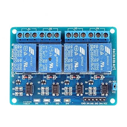
Kylen and I present müd: a lamp that senses the presence and temperature of someone's hand and displays the color of the mood that relates to that temperature! We have a photo cell in the palm which senses light; if it's covered, the three thermistors at the fingertips will begin to read the temperature. Once the photo cell is covered, and the loop of colors has completed, the light turns bright white. Once the temperature is read, the color switches to the color which relates to this temperature; the chart of the colors and the related moods (emoji) is included below.


https://vimeo.com/169797098

code:
//Libraries
#include <Adafruit_NeoPixel.h>
#include <math.h>

//Converting thermistor input to degrees F
double Thermistor(int RawADC) {
 double Temp;
 Temp = log(10000.0*((1024.0/RawADC-1))); 
 Temp = 1 / (0.001129148 + (0.000234125 + (0.0000000876741 * Temp * Temp ))* Temp );
 Temp = Temp - 273.15;          
 Temp = (Temp * 9.0)/ 5.0 + 32.0; 
 return Temp;
}

//Photocell
int photocell = 0;

//Lights
int LED = 9;

//Neopixel Setup
#define PIN 9
Adafruit_NeoPixel strip = Adafruit_NeoPixel(8, PIN, NEO_RGB);

void setup() {
  strip.begin();
  strip.show(); //Initializa all pixels to 'off'

  pinMode(LED, OUTPUT);
  pinMode(A1, INPUT);
  Serial.begin(9600);
}


void loop() {
  int val;
  double temp;
  photocell = analogRead(A1); //photocell is A1

  //Read thermistor values
  int sensorValue=analogRead(A3);
  int sensorValue2=analogRead(A4);
  temp=Thermistor(sensorValue/2 + sensorValue2/2);

  //Print temperature
  Serial.print("Temperature = ");
  Serial.print(temp);
  Serial.println(" F");
  delay(1000);

  if (photocell < 200) {
    for (int i; i<7; i++) {
      strip.setPixelColor(i, 255, 255, 255);
    }
    
   }
else {
    if (temp < 80) {
      strip.setPixelColor(0, 255, 0, 0);
      strip.setPixelColor(1, 255, 0, 0);
      strip.setPixelColor(2, 255, 0, 0);
      strip.setPixelColor(3, 255, 0, 0);
      strip.setPixelColor(4, 255, 0, 0);
      strip.setPixelColor(5, 255, 0, 0);
      strip.setPixelColor(6, 255, 0, 0);
      strip.setPixelColor(7, 255, 0, 0);
      //Red when the photocell is covered, and temperature is below 80 degrees
      delay(10);
    }

  else if (temp > 80 && temp <= 87) {
    strip.setPixelColor(0, 0, 255, 0);
    strip.setPixelColor(1, 0, 255, 0);
    strip.setPixelColor(2, 0, 255, 0);
    strip.setPixelColor(3, 0, 255, 0);
    strip.setPixelColor(4, 0, 255, 0);
    strip.setPixelColor(5, 0, 255, 0);
    strip.setPixelColor(6, 0, 255, 0);
    strip.setPixelColor(7, 0, 255, 0);
    //Green when the photocell is covered, and temperature is between 80 and 87 degrees
    delay(10);
  }

  else if (temp > 87 && temp <= 92) {
    strip.setPixelColor(0, 0, 0, 255);
    strip.setPixelColor(1, 0, 0, 255);
    strip.setPixelColor(2, 0, 0, 255);
    strip.setPixelColor(3, 0, 0, 255);
    strip.setPixelColor(4, 0, 0, 255);
    strip.setPixelColor(5, 0, 0, 255);
    strip.setPixelColor(6, 0, 0, 255);
    strip.setPixelColor(7, 0, 0, 255);
    //Blue when the photocell is covered, and temperature is between 87 and 92
    delay(10);
  }

  
  }
  

  Serial.println(photocell);
  strip.show();
}