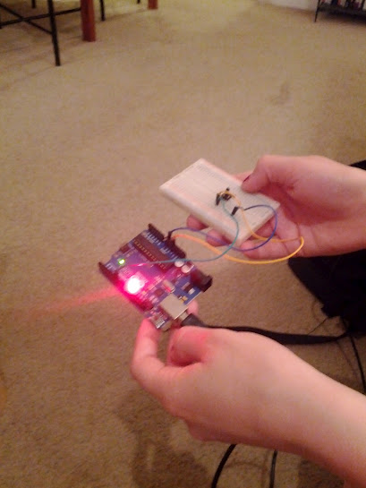
As computing becomes more ubiquitous in our objects, designers need to be more aware of how to design meaningful interactions into electronically enhanced objects. At the University of Washington, a class of junior Interaction Design majors is exploring this question. These pages chronicle their efforts.

Monday, April 30, 2012

Sheema & Claire Arduino Adventures: THERMITOR AND FAN

We were able to control a fan based on the temperature the sensor read.

A thermitor sensor detects ambient temperature and temperature changes. For this example we used this temperature sensor to turn on a fan whenever the programed temperature was reached.

Here is a video of the interaction of the thermitor sensor with the fan. When the desired temperature was reached the fan would turn on and whenever the temperature was under that of the desired, the fan would shut off.


There were many ways to conduct enough heat to warm up the thermitor sensor and start the fan, the easiest and fastest we found was covering the sensor with our hands, warming it up immediately. The next option was holding a lamp above the sensor, which depending on the temperature it needed to reach took a considerably longer time to achieve. The temperature could be lowered, and therefore result in the stopping of the fan by either removing ones fingers, or blowing on the sensor, lowering the temperature.

The code originated from the Getting Started with Arduino, 2nd Edition reader. We then manipulated the code to incorporate the thermitor sensor as well as conduct the reaction of the fan to the temperature.


The lights on the fan started in unison when the fan started.


Here is our code:

#include <math.h>

const int FAN = 9; //location pin of fan

/* This function determines a temperature in degrees Farenheit from the raw
data accumulated by the thermistor */
double Thermister(int RawADC) {
 double Temp;
 Temp = log(((10240000/RawADC) - 10000));
 Temp = 1 / (0.001129148 + (0.000234125 + (0.0000000876741 * Temp * Temp ))* Temp );
 Temp = Temp - 273.15;            // Convert Kelvin to Celcius
 Temp = (Temp * 9.0)/ 5.0 + 32.0; // Convert Celcius to Fahrenheit
 return Temp;
}

void setup() {
 pinMode(FAN, OUTPUT); //set up fan as output
 Serial.begin(115200); //start therm readings
}

void loop() {
if (Thermister(analogRead(0)) > 70) {  //if therm temp is greater than 70
analogWrite(FAN, 0); // turn fan ON
}
else {
analogWrite(FAN, 255); // turn fan OFF
}

}


Kelly and Aaron: A Non-LED Actuator

This week we decided to try using our PIR motion sensor from last week with a new actuator. Instead of an LED, we now have a Piezo Buzzer! We used the buzzer to create a more nerve-wracking version of Red Light, Green Light: the green still means go, but when the sensor catches you, it now buzzes in F# until you freeze. Our setup is pretty similar to last week, as you can see in this photo:


Check out our code below:

const int BEEP = 9; // the pin for the beeper
const int GREEN = 8; 
const int SENSOR = 7; // the input pin where the pushbutton is connected 
int val = 0; // val will be used to store the state of the input pin 
void setup() 
{
pinMode(BEEP, OUTPUT); // tell Arduino LED is an output 
pinMode(SENSOR, INPUT); // and BUTTON is an input 

void loop(){ 
val = digitalRead(SENSOR); // read input value and store it // check whether the input is HIGH (button pressed) if (val == HIGH) 

digitalWrite(GREEN, LOW); 
tone(9, 2800); // turn LED ON 
} else { noTone(9); 
if (val == LOW) 

digitalWrite(GREEN, HIGH); // turn LED ON } 
else { digitalWrite(GREEN, LOW); 


}

Sheema & Claire Arduino Adventures: FADE

Controlling the brightness of an LED with a pushbutton.

We began by hooking up the Arduino and breadboard with an LED connected with PWM pin, as shown in Getting Started with Arduino, 2nd Edition.

After we successfully connected it, we then connected the pushbutton to the breadboard.

Having both the pushbutton and the LED both connected to the Arduino through the ground circuit provides power and ground where it is needed to make them work.

Clicking the pushbutton results in the fading of the brightness of the LED.


The picture does not do it justice, the LED would turn on when pressed and fade out.


Check out our code:

// Example 02: Turn on LED while the button is pressed

const int LED = 13; // the pin for the LED
const int BUTTON = 7; // the input pin where the
// pushbutton is connected
int val = 0; // val will be used to store the state
// of the input pin
void setup() {
pinMode(LED, OUTPUT); // tell Arduino LED is an output
pinMode(BUTTON, INPUT); // and BUTTON is an input
}
void loop(){
val = digitalRead(BUTTON); // read input value and store it
// check whether the input is HIGH (button pressed)
if (val == HIGH) {
digitalWrite(LED, HIGH); // turn LED ON
} else {
digitalWrite(LED, LOW);
}
}

Thursday, April 26, 2012

Reema + Jill: Arduino Research & Sensors

After our last critique, we decided to go in a completely new direction. Although our bike idea was compelling, it would be too complicated to execute. Our new idea is a cup holder (similar to a coffee sleeve) that tells the user when their beverage is at the perfect temperature.

World: Someone has a hot beverage and doesn't know when it has cooled down enough. They don't want it to be too cold either, so finding the ideal temperature is very important.
Input: Person touching/holding the cup. The heat of the beverage.
Sensor: A capacitive touch sensor senses when the cup is being held or touched. An analog temperature sensor is measuring the heat of the beverage.
Brain: The brain must interpret the temperature as being to hot, just right, or too cold. It also must pick up on the cup holder being touched and be able to tell the actuators how to react.
Actuator: Depending on the temperature, an LED lights up (red for too hot, green for just right, and blue for too cold) and a speaker plays one of three audio samples (with lyrics relating to the temperature of the beverage).
Output: The person can drink their beverage at the perfect temperature!

After browsing the internet, we tried to make our own capacitive touch sensor using an aluminum can:


/*

This code turns the LED on while the sensor is in contact
with a conductive material (e.g. when someone touches it
with their bare skin/fingers)

Setup:
Attach a high value resistor (1-10M Ohm) between an output
pin 4 and input pin 5. Also connect a short bare copper or
aluminum wire/foil to the input pin5. Connect an LED to
output pin13 and GND.

By: Naureen Mahmood.

*/

#define LED        13
#define THRESHOLD   5

int capI;      // interval when sensor pin 5 returns LOW

void setup()
{
  Serial.begin(9600);
  pinMode(LED, OUTPUT);
  pinMode(4, OUTPUT);     // output pin
  pinMode(5, INPUT);      // input pin
}

void loop()
{
  capI = 0;      // clear out capacitance measure at each loop

  // transition output pin4 LOW-to-HIGH  to 'activate' sensor pin5
  digitalWrite(4, HIGH);     

  // On activation, value of pin 5 stays LOW for a time interval T = R*C.
  // C is big if the sensor is touched with a conductive object.
  // Increment capI for the interval while pin5 is LOW
  int val = digitalRead(5);  // read the input to be checked
  while (val != HIGH){   
    capI++;   
    val = digitalRead(5);    // re-read the input to be checked
  }
  delay(1);
  // transition output pin4 HIGH-to-LOW to 'deactivate' sensor pin5
  digitalWrite(4, LOW);     
  Serial.println(capI, DEC);  // print out interval

  if (capI > THRESHOLD)       // Turn LED on if capI is above threshold
    digitalWrite(LED, HIGH);
  else 
    digitalWrite(LED,  LOW);
}

BRIDGET/SHELBY (BS) vs. ARDUINO, part the third

For this installment of BS vs. ARDUINO, our as yet undefeated victors/heroes challenge Arduino UNO to a fierce battle of wits. The Arduino has chosen his weapon, and he has decided to defend himself with... a CDS photocell!!! Team BS has proven itself to be a fearless competitor in the ring, but this is a great challenge, indeed! We are excited to see this play out!

 Team BS gears up for the big fight against the mighty Arduino by plugging in the photocell, LEDs, and resistors into the breadboard, hooking it up to the Arduino with breadboard wires.


Then they write the code to correspond with the setup of all of the elements. In an attempt to make two LEDs react in opposite ways to light or darkness being sensed, they base their code off of a simple photocell test sketch, and use two analogWrite functions to make one fade and one brighten (the second argument of the function was positive for one, negative for the other). They face a bit of difficulty in figuring it all out, but they manage to pull it off!


Low light (finger covering photocell, blue light bright/green light dim):


Bright light (room light, blue light dim/green light bright):


Arduino + sensor, defeated!

(video to come soon)

Kelly and Aaron: Push Button, Fade, Motion, and More!

Last week we did the Push Button exercise, and this week we did it again. You can find the documentation here!

Next up, we worked on fading our LED. This was a pretty straightforward experiment, see ours here:


 After that, we decided to choose a PIR sensor (an infrared motion sensor) to experiment with. We first made a simple motion-detector, which lights up a red LED when it detects any motion. We based our code off the initial push-button code and modified it to work with our new sensor. Not as hard as we would have expected! Check out Aaron testing it out:


 Finally, we wanted to push our experiment a little further. We combined what we learned in class last week with our alternating LED "cop lights" with our new PIR sensor to create what is essentially an Arduino-run game of Red Light, Green Light. Here's our infomercial:


 When motion was detected, the red LED turns on, and when no motion is detected, the green LED switches on while the red LED turns off. This let us learn exactly how sensitive the PIR sensor was: extremely sensitive! It sensed almost any tiny movement within 30 feet in front of it, even with furniture in the way. We were very impressed with the fidelity of sensor available for $10 at our local Radio Shack! If you want to test our or modify our code for this, try it out below:

const int LED = 13; // the pin for the LED
const int LEB = 8;
const int BUTTON = 7; // the input pin where the // pushbutton is connected
int val = 0; // val will be used to store the state // of the input pin
void setup() {
pinMode(LED, OUTPUT); // tell Arduino LED is an output
pinMode(BUTTON, INPUT); // and BUTTON is an input
} void loop(){
val = digitalRead(BUTTON); // read input value and store it
// check whether the input is HIGH (button pressed)
if (val == HIGH) {
digitalWrite(LEB, LOW);
digitalWrite(LED, HIGH); // turn LED ON
} else {
digitalWrite(LED, LOW);
if (val == LOW) {
digitalWrite(LEB, HIGH); // turn LED ON
} else {
digitalWrite(LEB, LOW);
}
}
}

Claire & Sheema: Pressure Sensor & LED

We used a pressure sensor to detect how hard someone is squeezing and then adjust the LED accordingly. If you don't squeeze too hard the LED turns on and says on until you let go. But if you squeeze harder, the LED will start blinking. 


LED will start blinking if squeeze even harder. 


// Exercise : Pressure Sensor and LED

int LED = 13; // LED connected to digital pin 13
int sensorPin = A0;
int sensorValue = 0;

void setup()
{
  pinMode(LED, OUTPUT); // sets the digitalpin as output
}

void loop()
{
  sensorValue = analogRead(sensorPin);
  if (sensorValue >100 && sensorValue <=600)
  {
    digitalWrite(LED, HIGH); // turns the LED on
  }
  else if (sensorValue >600)
  {
    digitalWrite(LED, HIGH); // turns the LED on
    delay(100); // waits for a second
    digitalWrite(LED, LOW); // turns the LED off
    delay(100); // waits for a second
  }
  else
  {
    digitalWrite(LED, LOW); // turns the LED off
  }
}


Charissa + Erin: Sensory

The motor is operated via the bending and flexibility of the sensor. 


This is a movie of sensory in action:


Miles & Kim: Motion Sensor Experiment

For our sensor we chose to use a PIR Motion Sensor. The sensor detects motion using infrared and lights up during movement. We started with a sketch called PIR Sensor Tester, which detects motion and prints "Motion Detected" in the serial monitor. We altered the code to make the LED fade in and out, and have a blue LED be on when no motion was detected.

Here is the code we used:


/*
 * PIR sensor tester
 */

const int ledPin = 9;           // choose the pin for the LED
const int bluePin = 6;
int inputPin = 2;               // choose the input pin (for PIR sensor)
int pirState = LOW;             // we start, assuming no motion detected
int val = 0;                    // variable for reading the pin status
int i = 0;

void setup() {
  pinMode(ledPin, OUTPUT);      // declare LED as output
  pinMode(bluePin, OUTPUT);
  pinMode(inputPin, INPUT);     // declare sensor as input

  Serial.begin(9600);
}

void loop(){
  val = digitalRead(inputPin);  // read input value

  if (val == HIGH) {            // check if the input is HIGH
   
    if (pirState == LOW) {      // we have just turned on
      Serial.println("Motion detected!");  // We only want to print on the output change, not state
      pirState = HIGH;
     
      for(i = 255; i >= 0; i--) {
        analogWrite(bluePin, 0);
        analogWrite(ledPin, (255 + -i));
        delay(10);
      }
     
      /*for(i = 0; i < 255; i++) {
        analogWrite(ledPin, i);
        delay(10);
      }
      */
    }
     
  } else {
    //digitalWrite(ledPin, LOW); // turn LED OFF
   
    if (pirState == HIGH){     // we have just turned of
      Serial.println("Motion ended!"); // We only want to print on the output change, not state
      pirState = LOW;
     
      for(i = 255; i >= 0; i--) {
        analogWrite(ledPin, 0);
        analogWrite(bluePin, (255 + -i));
        delay(10);
      }
     
     /* for(i = 0; i < 255; i++) {
        analogWrite(bluePin, i);
        delay(10);
      } */
    }
  }
}

Here is a video of our code in action:


Ryan and Dave - Analog input using a flex sensor

This week we started to explore analog input. Using sketch 6b - "Set the brightness of LED to a brightness specified by the value of the analogue input" we included a flex sensor - a sensor whose resistance changes with the amount it is flexed. Note the difference in LED output.


Ryan and Dave - Adding a push button and other resistors to the circuit.


After the difficulty of last week’s build that we ultimately tracked down to a faulty lead, we decided to bring out my multi-tester before we got started. I definitely recommend having one of these on hand. It’s great for checking suspect components and peeking inside the circuit, although I definitely recommend a digital model for the precision it offers. 

A decent multi-meter isn't expensive, this one is $17.25 on
Amazon, and serviceable digital models can be found for $5-$6.

The suspect lead from last week.
Checking the meter to verify it’s working correctly, it should
read close to zero. The meter is set to read ohms (resistance).
No continuity
Into the trash with you!
Sketch 2 - Everything seems to be working. 

A close up of the breadboard.

Before modifying the program, we wanted to try some variations on the circuit 
that might yield similar results to upcoming sketches so we moved the LED to 
the breadboard.

The potentiometer is connected using one pole and the wiper – technically a
variable resistor.

Dialing it down. (The multi-meter read about 100 ohms at this setting) 

There’s not much change to the light output after this point. 

Same thing with a photo-resistor.

Sketch 3x - “Look Ma, no hands”

Sketch 5 - Combining two circuits to turn on AND adjust LED brightness with one button.


Wednesday, April 25, 2012

Shelby and Bridget: push button and fade

After our first assignment, we were very excited and moved on to the push button exercise, which we documented in our last post. We were so excited that we did it again.

The setup:


Not pressing the button:


Pressing the button:


The we wrote the appropriate code for the LED to fade and brighten with a 50 millisecond delay, and we plugged in everything appropriately. Super shiny!


Bright:


Faded (oops, finger!):


Shelby and Bridget: Winners!

Tuesday, April 24, 2012

Reema + Jill: Pushbutton and Fade Demos


Reema Bhagat and Jill Moses
Arduino Demonstration 2

Using a Pushbutton to Control the LED
We first plugged in all of the necessary components for the push button demonstration. This included connecting the button and resistor into the breadboard and then adding the wires to the Arduino, as well as the breadboard. Next, we plugged in the USB to the Arduino and our computer, after adding the code. We then verified and uploaded our code and pushed the button to make sure it worked. The red LED that we plugged in turned on when the button was pushed and turned off when it was released. The code worked and the demonstration was a success.

We then tried example three in the book: Turning on the LED when the button is pressed, and keeping it on after it’s released. After uploading the code and verifying, we tested it. The LED stayed on after the button was pressed and stayed on until the button was pressed for a second time. Our button was somewhat loose on the breadboard, so the demonstration only worked correctly some of the time.


Fading an LED in and out, like on a sleeping apple computer
First, we built the circuit by re-configuring the wires, resistor and LED on the breadboard. Next, we created a new sketch on the computer, putting in the new code for the demonstration. We verified and uploaded the sketch, and the demonstration worked well. We then wanted to play with the code and modify the fade time, so we experimented with several iterations of that. We experimented with making the “fade in” time to be longer, and the “fade out” time to be shorter. The rhythm of the fade was altered as a result of our experimentation as well. 


Charissa and Erin's Arduino Experiments

Here is a link to our fading LED version. Charissa and I completed the in class demonstration during the previous week. Visit our last post for details on our process.

Interested in our experimental version? Check out this link with our knob adjusting LED!

Here is a diagram Charissa developed to illustrate how we set up our Arduino bread board and connectors to adjust for brightness:


Interested in our code?


Thanks!

Miles & Kim: Arduino Experimentation Round Two

For our second round of experimentation with the Arduino we used Fade and pushButton, and then further manipulated the examples to see what they could do and what the different components of code effected. We began with walking through the previous steps from last post's experiments. We hooked the Arduino Uno up to the computer through the USB port, and uploaded the sketch from each example. This time, it was slightly different, however, because we also needed to use a breadboard, switch, and a resistor. Each exercise required the LED or the switch to be placed on the breadboard, with two wires connecting into the correct pints on the Arduino.

Here is our completion of pushButton:


Here is our completion of Fade:


When we completed each of these examples we played with the code to see what else we could do. We began with altering the delay in Fade. We changed it first to 80, prolonging the "fade" effect, and then to 10, causing the flashing to occur at a faster rate. We then considered combining the original Blinking LED exercise with Fade, so we put code into the loop that would make the LED flash while simultaneously fading. Here is the code to achieve that:


/*
 Fade

 This example shows how to fade an LED on pin 9
 using the analogWrite() function.

 This example code is in the public domain.

 */
int brightness = 0;    // how bright the LED is
int fadeAmount = 5;    // how many points to fade the LED by

void setup()  {
  // declare pin 9 to be an output:
  pinMode(9, OUTPUT);
}

void loop()  {
 
  // set the brightness of pin 9:
  analogWrite(9, brightness);  

  // change the brightness for next time through the loop:
  brightness = brightness + fadeAmount;

  // reverse the direction of the fading at the ends of the fade:
  if (brightness == 0 || brightness == 255) {
    fadeAmount = -fadeAmount ;
  }    
  // wait for 30 milliseconds to see the dimming effect  

  delay(30);
  digitalWrite(9, HIGH);   // set the LED on
  delay(500);              // wait for a second
  digitalWrite(9, LOW);    // set the LED off
  delay(500);              // wait for a second

}

Unfortunately, the flashing appears to overpower the fade. We think this is because it runs through the fade loop so quickly that it goes unnoticed and without feedback from the device.

We then commented out the new flashing code, and decided to mess with the brightness to see what effect it had. We realized that changing the "255" did not make it brighter or less bright directly, but instead stopped the flashing earlier, changing the rhythm of the fade.

Thursday, April 19, 2012

Reema + Jill: Sensor_Using a Potentiometer

We wanted to experiment with different sensors and controlling analog input. We experimented with using a potentiometer to control the rate at which the LED (that we connected) blinked. First, we connected our wires to the Arduino board. The first wire went from ground to one of the outer pins of the potentiometer. The second went from five volts to the other outer pin of the potentiometer. The third went from analog input zero to the middle pin of the potentiometer. We attached an LED as well, and connected it to the Arduino board at pin thirteen. After we put in our code, turning the knob of the potentiometer adjusted the rate at which the LED blinked. We then experimented with the sensorValue in the code, which is the variable that stores the value coming in from the sensor. See our code and images below.