Physical Computing 325 Final
University of Washington
Jack Kramer

For my final project, I decided to make an arduino modulated humidity responsive plant germination unit. The original plan was to use a photoresistor to determine when the grow light would turn on, as well as a homemade humidity sensor to send data to an LCD as a means of alerting me when I need to water the plant. I got a little over halfway there before I killed my power supply, this is my journey.
I started with the grow lights. I bought some inexpensive basic lights off Amazon, there wasn’t anything super special about these other than the fact that they had an easy clamp attachment mechanism. I didn’t know it at the time, but these lights are actually powered through a USB wall adapter, which meant they could be powered off a 5V lead.
Before I could do anything else, I needed to snip off the USB power connection and gain access to the 5V and ground wires. I snipped above the light timer that came with the unit; I didn’t want the internal control unit to mess with the voltages or program, so I just cut above.

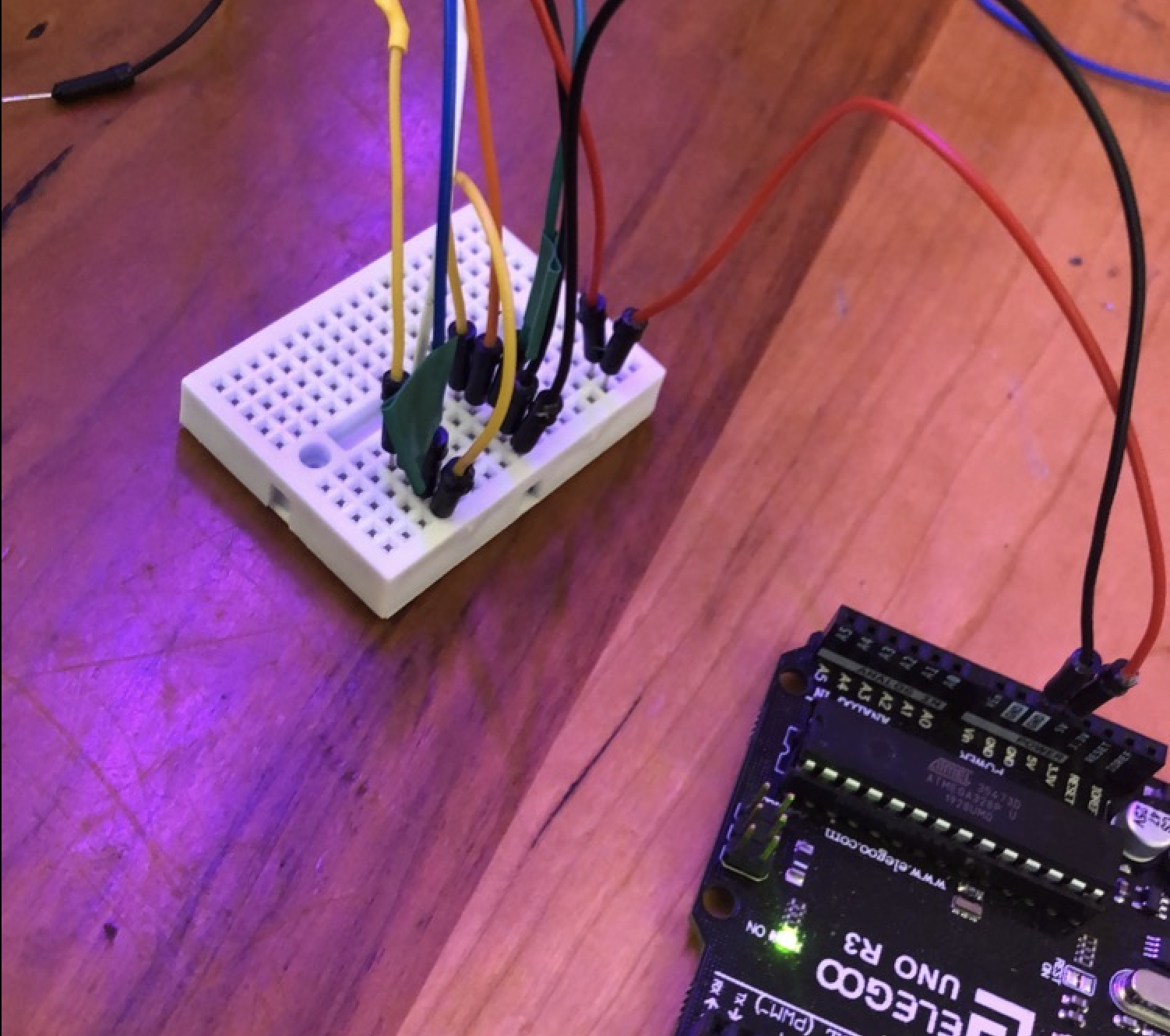
In an unexpected twist, I got seven wires instead of two. Red, green, black, blue, yellow, brown, and white. Through some trial-and-error I was able to determine which were grounds and which were power, which I organized on the mini breadboard that came with the arduino kit.

I then proceeded to plug the 5V into the 5V lead on the Arduino and the ground on the Arduino GND, and it worked! I knew my solder job was solid and I got all the leads right.
Unbeknownst to me, this was actually a huge problem. The arduino was built for control, not power; I needed to power the lights with an external power supply AND build a relay circuit to control the voltage.
I used this guide to build the relay circuit using a Songle SRD-24VDC-SL-C. I encountered a small problem with the pinout, seeing how the relay provided with the kit didn’t come with a PCB to allow for easy setup. The one I got had five pins and ALL the guides used the PCB relay, which had six pins.
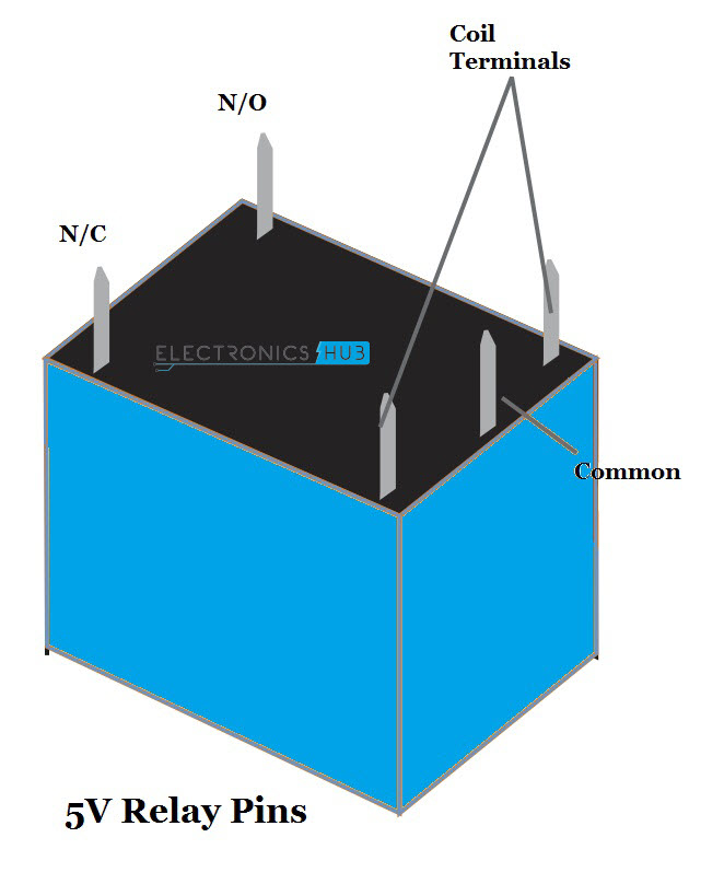

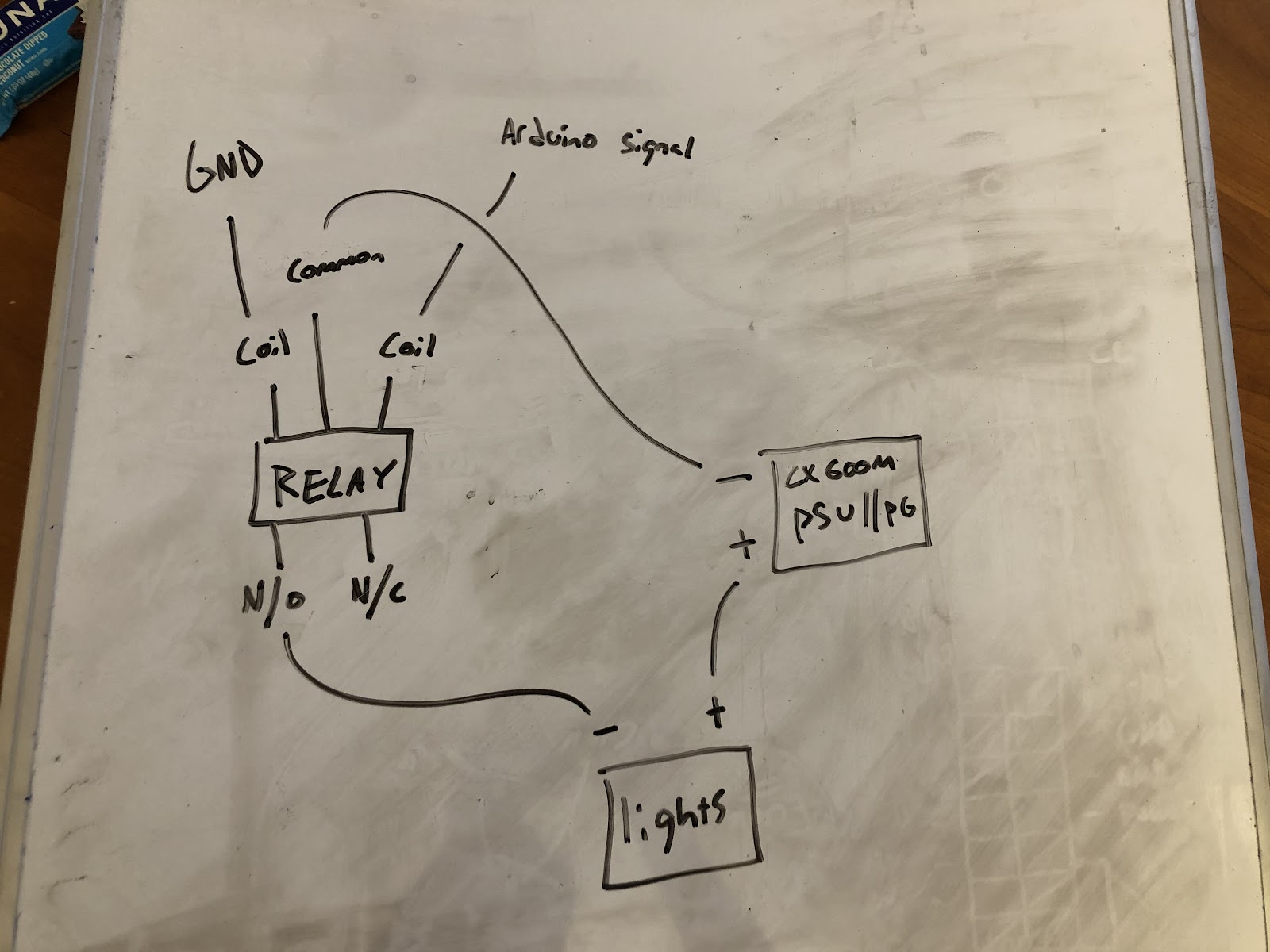
This actually turned out to be a pretty easy fix- the N/O (normally open) pin would go directly to the negative lead of the light, and the N/C (normally closed) pin would be left alone. One of the coil terminals would go to the ground lead on the breadboard, and the other would go to the arduino signal pin (I used ~10). Finally, the common pin would go to a GND pin on the external power supply, which would also provide a +5V lead to power the lights.
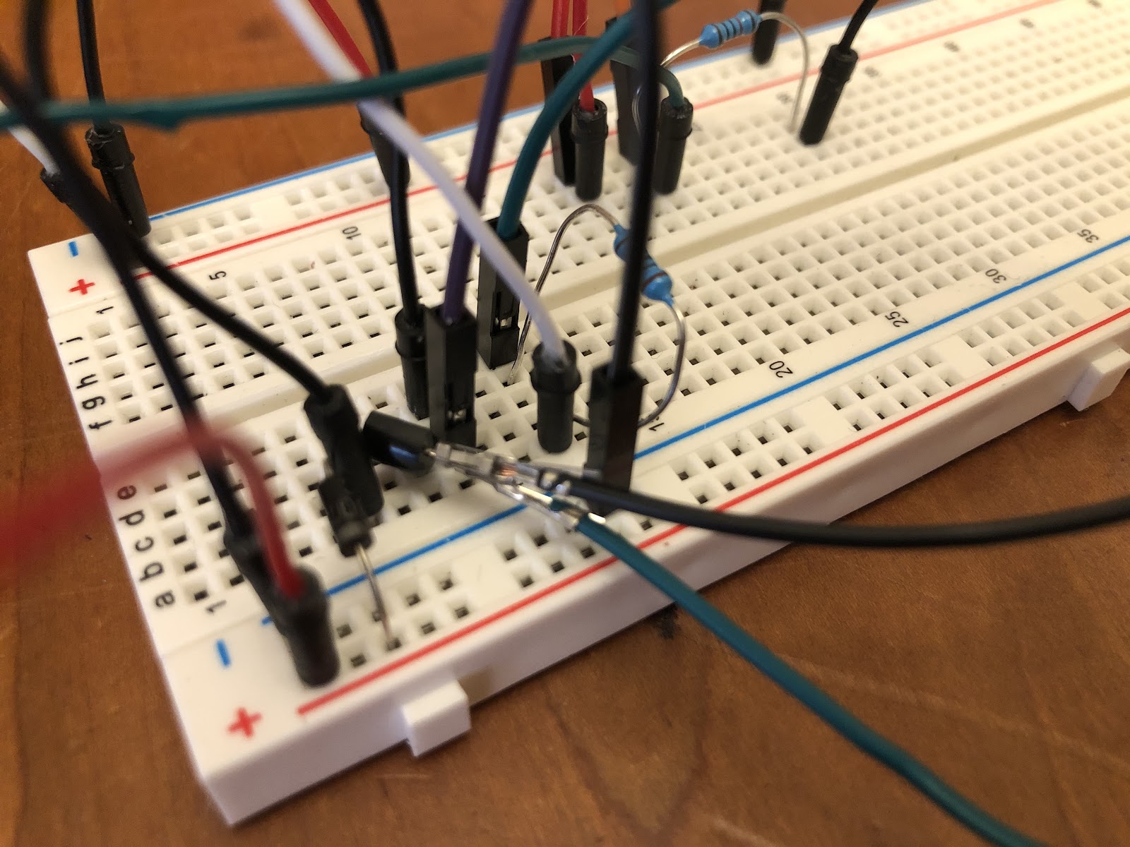
The final step was to get the 1N4007 diode and the 2N2222 transistor set up correctly, seeing how the PCB controlled version of the relay had it built in; this was simple and resulted in the following wiring:
Now I had to figure out a power supply to run everything. I gutted an old Dell and came up with this bad boy-

Dell doesn’t provide pinouts for their proprietary power supplies (PSU), so I had to use a multimeter to determine which pins provided which voltage on the H240EM-00. I came out with this pinout-

I couldn’t use the 4-pin, seeing how the 12V lead was way too powerful. I actually tried the circuit with the 12V, and after a couple seconds the mini breadboard started to smoke. A 5V was required. The 8-pin had more variation in the voltage outputs, but the only problem with this was that one of the two pins used to jump the PSU happened to be the +5V (green), so when I tried to use that lead it didn’t give any power to the circuit. The -5V didn’t work. I had to find another PSU.
Enter the Corsair CX 600 M.
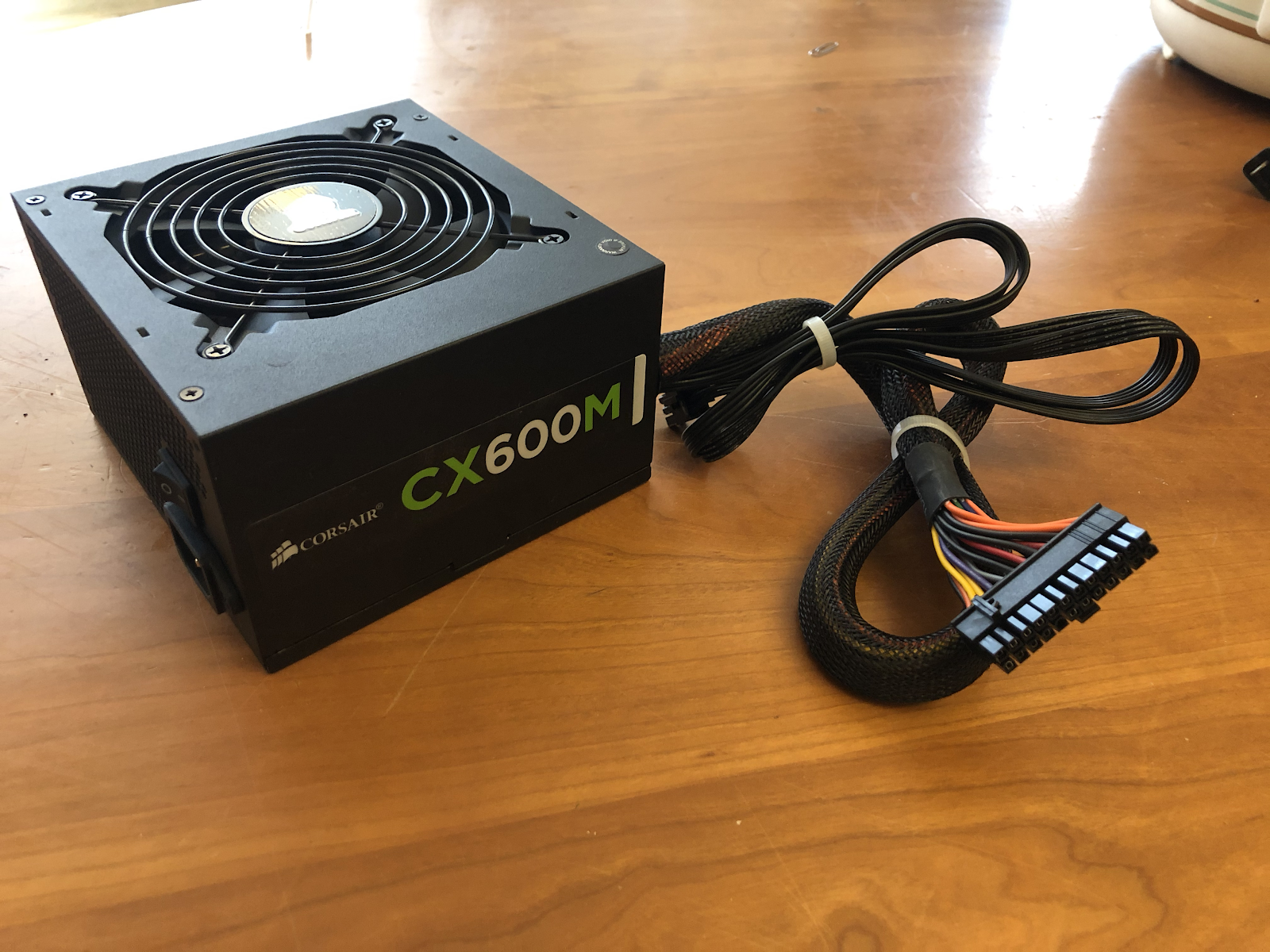
I didn’t care that it was three times as powerful as the Dell, all that mattered was that it had a standard ATX pinout, a diagram that was readily available on the internet. No more multimeter was needed.

Now I had unobstructed access to multiple +5V leads, seeing how the PS-ON pin was a standalone function pin. Perfect. The last step was to implement the photoresistor.

I connected it all with the following code!

This told the arduino to turn the lights on if the photoresistor received no light- when the sun set, the grow lights would turn on!
Now I started to work on the humidity sensor. There are premade soil sensors like this one, but I decided to make one out of screws using this guide. I started by taking two screws and some wires and soldering the wires to the screws after securing the wire to the screw with a nut.
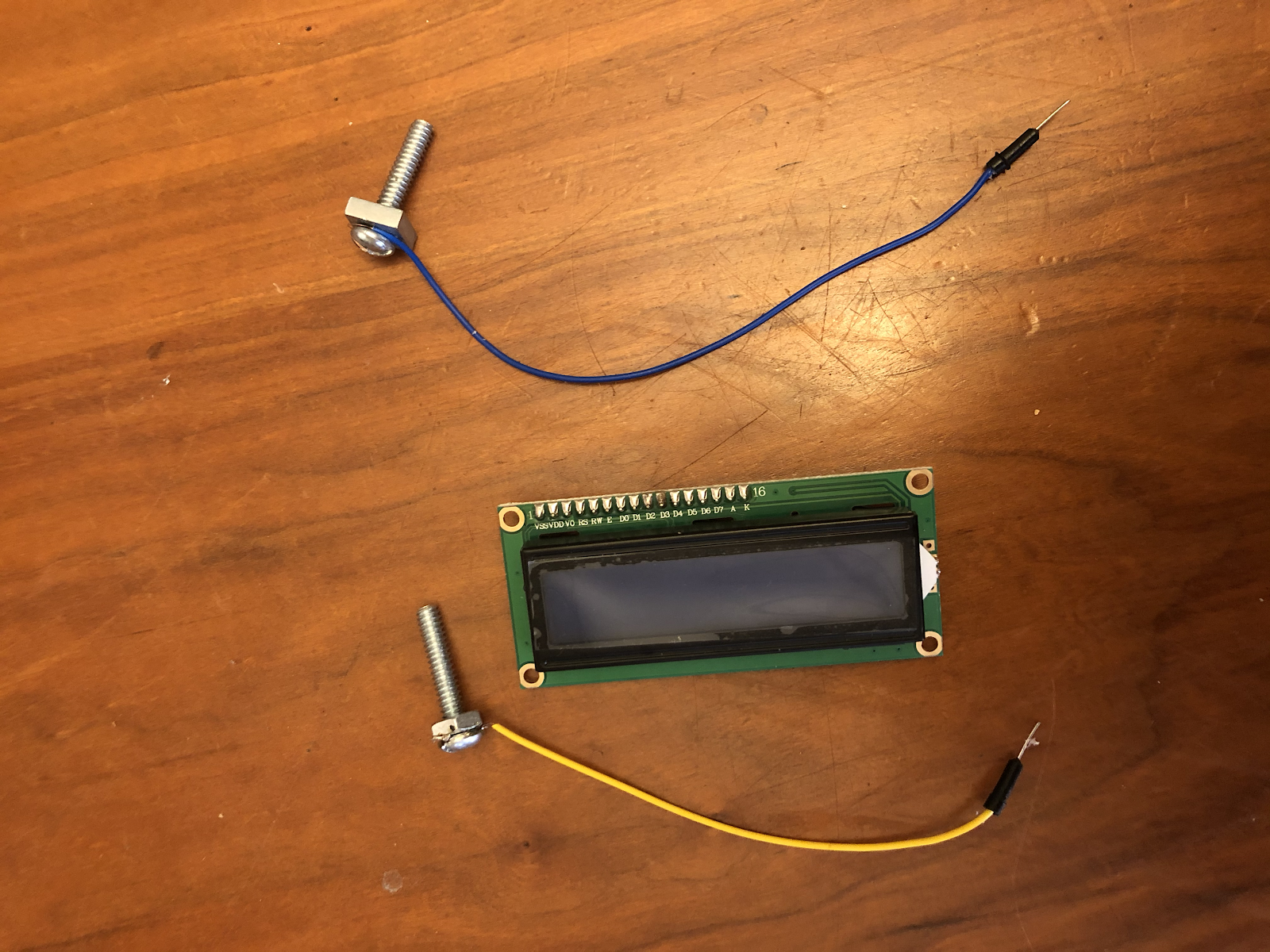
However, that’s as far as I got before the PSU killed itself. I don’t know what I did wrong, all I know is that it doesn’t turn on anymore.
If I had continued along, I would have used the guide above, combined with the LCD, to write out the sensor readings on another mini breadboard to produce an easy-to-read module to let me know when to water the plant, with the “digitalWrite” function could have been adapted to the LCD using the “lcdPrint” function.
A new PSU is on the way, we’ll see what happens :)
No comments:
Post a Comment